
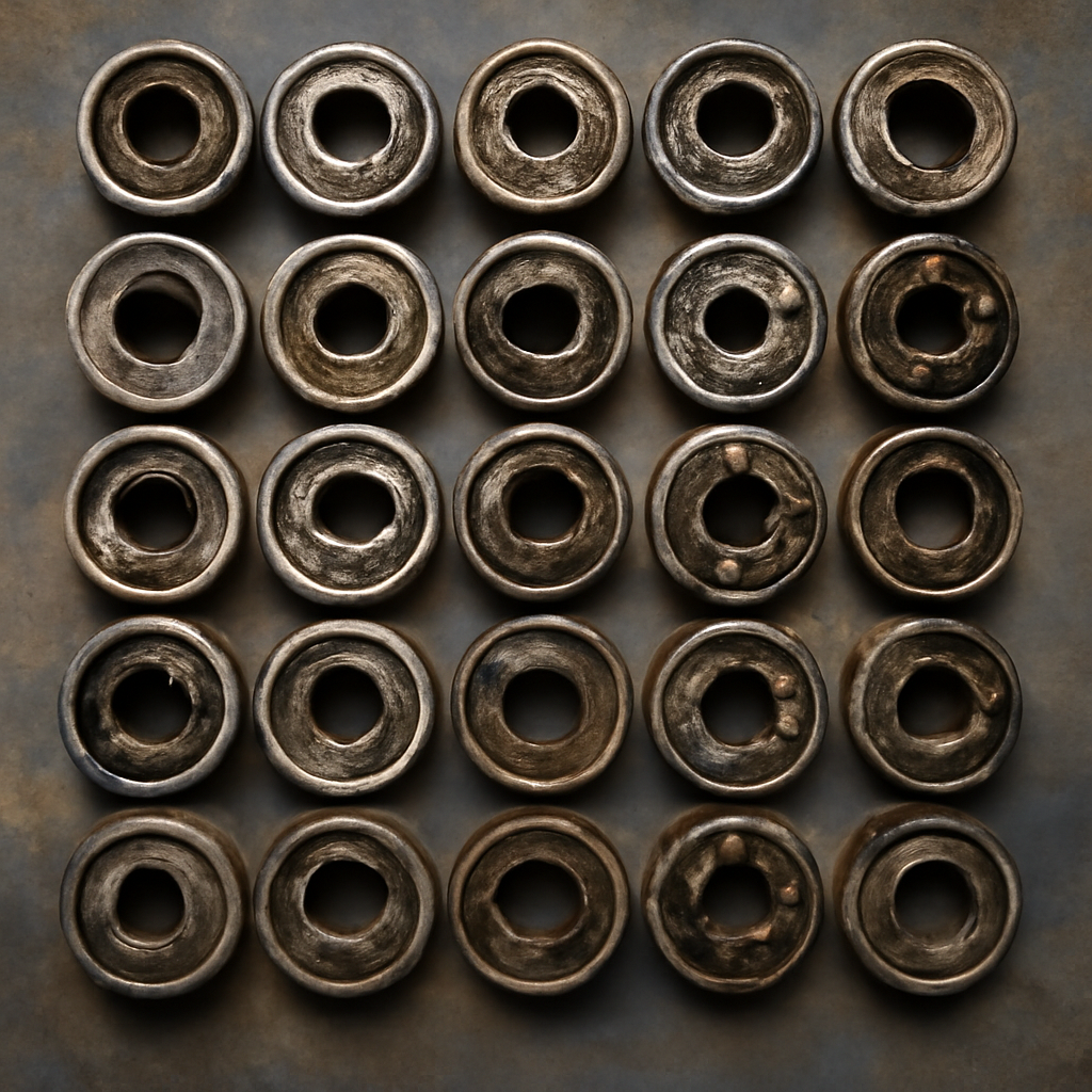
Every bearing failure leaves a visible signature on the raceways, rolling elements and cage. The trained eye recognises the signature; the untrained eye sees only “broken bearing”. The difference matters: identifying the failure mode tells you what caused it, and what to do about it. This guide builds a mental photo library of 30 distinct bearing failure patterns every maintenance technician should be able to recognise on sight. Combine this with systematic failure investigation and your bearing reliability improves measurably across the fleet.
Fatigue and end-of-life patterns (1-5)
1. Surface fatigue pitting (spalling) — outer race
Elliptical or circular pitted areas on the outer raceway. Classical end-of-life. The bearing reached its calculated L10 fatigue limit. Action: verify L10 calculation was appropriate for actual duty; if yes, planned replacement is normal.
2. Surface fatigue pitting — inner race
Similar to #1 but on the inner raceway. Same root cause. The slight pattern differences between inner and outer race fatigue tell you which ring is at the calculated life limit.
3. Subsurface fatigue cracks (white etching cracks, WEC)
Visible only under metallographic examination but manifests as premature raceway spalling. Particularly significant in wind turbine main bearings and high-power gearboxes. Action: material upgrade and lubrication strategy review.
4. Macro spalling (advanced fatigue)
Large flaked areas, multiple sites, sometimes connected. The bearing has run past Stage 4 condition monitoring into structural damage. Action: immediate replacement, investigate why condition monitoring missed earlier signals.
5. Race chipping at the edges
Chipped raceway edges, particularly near shoulder transitions. Often related to incorrect mounting clearance or rolling element edge stress. Action: review mounting practice and bearing internal design.
Installation damage patterns (6-10)
6. Brinelling (true)
Round indentations spaced at exactly rolling element pitch. Hammer marks or shock load on stationary bearing. Action: train installers; verify equipment design for shock load protection.
7. False brinelling
Similar pattern to true brinelling but with characteristic discoloration. Small-amplitude vibration of stationary bearing. Action: protect stored bearings from vibration; rotate stored shafts.
8. Press damage on rolling elements
Marks on balls or rollers from improper press loading during installation. Action: train technicians on correct mounting (force only on the appropriate ring).
9. Cocked bearing
Asymmetric wear pattern from bearing installed at angle to shaft. Action: train on proper alignment during installation.
10. Over-temperature mounting damage
Discoloration of raceways from excessive heating during thermal mounting. The bearing steel was tempered, losing hardness. Action: train on temperature limits (120 °C maximum for standard bearings).
Lubrication-related patterns (11-16)
11. Adhesive wear (smearing)
Metal-to-metal damage from inadequate lubrication. Material transfer visible on raceways. Action: review lubrication intervals and grease specification.
12. Lubricant starvation streaks
Parallel streak patterns on raceways from intermittent lubrication failure. Action: verify automatic lubrication system function or re-greasing discipline.
13. Burned grease residue
Hard dark residue in the bearing housing from grease that has been overheated. Action: review temperature monitoring and grease specification.
14. Grease wash-out
Cleaned-looking bearing with no remaining grease. Water washout in marine or wash-down applications. Action: switch to calcium sulphonate grease.
15. Grease thickener separation
Oil pooling separately from thickener in the housing. Incompatible thickeners mixed during re-greasing. Action: implement thickener compatibility discipline.
16. Additive depletion damage
Wear patterns appearing after extended service period. The grease lasted too long; additives depleted. Action: shorter re-lubrication intervals.
Contamination patterns (17-21)
17. Abrasive wear (matte raceway)
Generalised dull matte appearance from hard particle contamination. Action: upgrade sealing strategy; investigate contamination source.
18. Discrete particle indentations
Individual dents from large contaminant particles. Action: review filtration on circulating lubrication.
19. Water etching
Discoloration with pitting pattern from water ingress. Action: improve sealing; consider stainless variants.
20. Chemical attack
Discoloration without mechanical damage from incompatible chemistry. Action: review chemical compatibility tables; switch material.
21. Salt deposit accumulation
Crystalline deposits on raceways from marine or de-icing salt environments. Action: stainless construction; marine-grade grease.
Electrical damage patterns (22-25)
22. EDM fluting (electrical discharge machining erosion)
Washboard pattern of parallel grooves across raceway. Inverter-driven motor stray currents. Action: install insulated bearings (Insocoat) or hybrid (ceramic ball) variants.
23. Frosting from arc damage
Matte frosted appearance from many tiny arc events. Early-stage EDM damage. Action: investigate electrical isolation and grounding.
24. Discrete arc pits
Individual pit marks from larger arc events. Action: review motor grounding and lightning protection.
25. Welded material from severe arcing
Welded steel from extreme electrical events. Action: full electrical system investigation.
Mechanical overload patterns (26-30)
26. Asymmetric raceway wear
Wear concentrated on one side from misalignment. Action: laser alignment; soft-foot correction.
27. Crack initiation at high-stress points
Visible cracks at shoulder transitions or load zones from overload. Action: review applied load against rating.
28. Cage fracture
Broken cage segments. Shock load or vibration exceeding cage capacity. Action: select brass cage for shock-loaded applications.
29. Roller-end damage
Wear or damage at roller ends from misalignment on roller bearings. Action: alignment verification and bearing internal design review.
30. Rolling element fragmentation
Balls or rollers broken or fragmented. Catastrophic failure mode usually preceded by other warning signs. Action: investigate why earlier warnings were missed.
The systematic failure investigation process
- Photograph the bearing as removed, from multiple angles.
- Note position, orientation, and service hours.
- Sample the grease for analysis.
- Clean and inspect raceways, rolling elements, cage under magnification.
- Compare visible patterns against the failure mode catalogue.
- Identify primary failure mode and contributing factors.
- Document for trend analysis across the fleet.
- Implement corrective actions based on root cause.
Building team competence in failure recognition
Failure recognition is a craft skill that improves with practice. Maintenance organisations that systematically photograph and review every removed bearing build the team competence over time. Within 2-3 years of disciplined practice, the team’s failure mode identification accuracy improves dramatically — and so does the implementation of corrective actions that prevent the next failure of the same type.
The training value of the photo library
For maintenance training programmes, building an internal photo library of actual bearing failures from your own equipment is more valuable than generic stock photos. Each failure is documented with the equipment context, operating conditions, identified failure mode, and corrective action implemented. New technicians learn from real cases relevant to the actual fleet.
Integration with condition monitoring
Failure photo documentation feeds back into condition monitoring strategy. When a failure occurs, review the condition monitoring data leading up to it — did the data show the warning signs? If not, why? Refining alert thresholds and pattern recognition based on actual failure cases improves predictive maintenance accuracy over time.
Conclusion
The bearing failure photo library is one of the most valuable competence-building activities maintenance organisations can undertake. The 30 patterns above cover the vast majority of industrial bearing failures encountered in European industrial operations. Combined with systematic investigation, root cause analysis, and corrective action implementation, the failure photo library compounds across years into measurably better bearing reliability across the fleet.
Industry context
Failure-mode literacy is one of the largest maintenance-productivity gaps in European industrial plants. A 2025 European reliability benchmarking survey put the share of plants with formal bearing failure-mode training below 30%, and the share with photographic failure logs below 15%. The rest rely on operator memory and vendor-side incident reports that arrive weeks after the event, when the physical evidence has already been discarded. That gap has a measurable cost: repeat failures on the same asset, ambiguous warranty claims, and root causes buried under “installation error” as a catch-all category. The 30 patterns catalogued here form the working vocabulary of an experienced bearing failure analyst — building that vocabulary inside the plant is a leverage move, because every failure that gets correctly labelled feeds back into procurement, lubrication and mounting practice.
Long-term reliability factors
Turning failure-mode recognition into long-term reliability gains requires three habits that most European plants can adopt without new capital equipment. First, photograph every failed bearing at removal — inner race, outer race, cage and rolling elements — before the parts are cleaned or shipped. Second, record the operating context: hours since last regrease, ambient conditions, load profile, any recent process changes. Third, tag each incident with the failure mode from a controlled vocabulary, not free text, so patterns become searchable over multiple years. Plants that have institutionalised this loop typically see the top three failure modes concentrate to a handful of assets over the first year, which then focus the reliability engineering effort. The photo library is the input; the failure log is the compounding asset that pays the actual reliability dividend over a five-year horizon.
Finally, plants that build a searchable multi-year failure log almost always discover that a small number of asset classes and mounting configurations account for the majority of failures — the 80/20 pattern shows up reliably. That finding, in turn, focuses the reliability engineering budget on the assets that actually move the needle, converting the photo-library exercise into a data-driven capital-planning tool rather than a training exercise.
Related guides on Eurobearing
- Bearing Failure Modes Guide
- How to Detect Bearing Wear by Vibration
- How to Inspect After 24 Months
- Common Installation Mistakes
- Diagnose Failing Bearing in 10 Minutes
Need help with bearing selection? Our team supports you with cross-references and lead-times.