
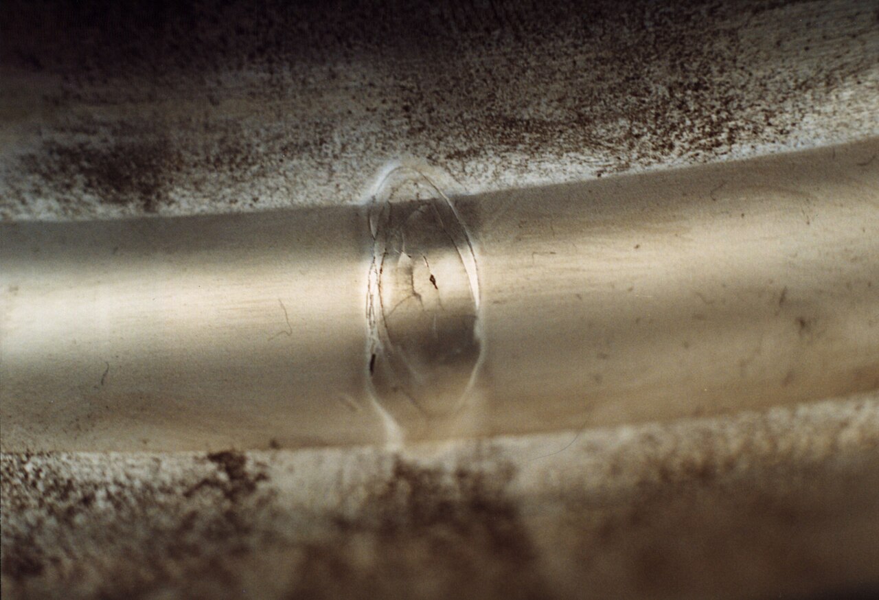
The spreadsheet on the planner’s screen said the conveyor head pulley bearings had a rated life of more than 50,000 hours, the scrap bin beside the workshop door said they were lasting about eighteen months, and the gap between those two numbers is exactly where ISO 281 bearing life calculations get misunderstood. Nobody had made an arithmetic error. The calculation was correct for the inputs it was given: a steady radial load, a constant speed, a clean and adequately lubricated bearing, and a statistical definition of failure that many buyers never read. The reality on site involved belt tension spikes, limestone dust and relubrication done whenever someone remembered. Before you order a bearing on the strength of an L10h figure, whether it comes from a catalogue calculator or an OEM data sheet, it pays to understand what the number is built from, which corrections the standard allows, and which real-world causes of failure it simply cannot see. This article walks through the formula, an illustrative worked example and the limits.
The basic rating life formula and its exponent
ISO 281 defines the basic rating life L10 as the number of revolutions, in millions, that 90 per cent of a sufficiently large group of apparently identical bearings will complete or exceed before the first evidence of rolling contact fatigue appears. The formula is short: L10 = (C/P)^p, where C is the basic dynamic load rating published by the manufacturer, P is the equivalent dynamic bearing load, and the exponent p is 3 for ball bearings and 10/3 for roller bearings. The exponent is what makes the calculation so sensitive. For a ball bearing, halving the load multiplies the rated life by eight, while increasing the load by about 26 per cent halves it. For a roller bearing the effect is slightly stronger: a 20 per cent load increase cuts life to roughly 54 per cent of its previous value. This is why an apparently small underestimate of belt pull, gear separating force or out-of-balance load produces large errors in the life figure, and why the load assumptions deserve more scrutiny than the catalogue C value.
From revolutions to hours: why speed matters as much as load
Revolutions are the natural unit for fatigue, but nobody plans maintenance in millions of revolutions, so the standard converts L10 into hours: L10h = (10^6 / (60 n)) × L10, with n the rotational speed in revolutions per minute. The conversion is linear, which often surprises people. A bearing running at 3,000 rpm has exactly half the hours of the same bearing at 1,500 rpm under the same load, because it accumulates stress cycles twice as fast. When a motor is changed from four-pole to two-pole, or an inverter pushes a fan above its original speed, the hour figure drops even though the load is unchanged. The opposite holds for slow, heavily loaded equipment such as kiln support rollers, where very low speeds produce large hour figures and the real concerns shift to static capacity and lubricant film formation. There the static safety factor, the ratio of the static load rating C0 to the equivalent static load P0, is often the more decisive check, and any selection based on load and speed has to weigh both.
Equivalent dynamic load: turning real forces into P
Real bearings rarely see a pure radial load, so ISO 281 combines radial and axial forces into a single equivalent dynamic load, P = X·Fr + Y·Fa, where Fr and Fa are the radial and axial components and X and Y are factors that depend on the bearing type and on the ratio between the two forces. For deep groove ball bearings the catalogue gives a limiting ratio e. While Fa/Fr stays at or below e, X is 1 and Y is 0, so a modest axial load is simply ignored. Once Fa/Fr exceeds e, X drops to 0.56 and Y takes a value typically somewhere between about 1.0 and 2.3, depending on how large the axial load is relative to the static rating C0. Tapered roller and angular contact bearings add a further step, because the radial load itself induces an internal axial force that has to be balanced between the two bearings of the arrangement. Getting P wrong is the most common source of misleading life figures, far more often than any error in C.
An illustrative example with a 6208
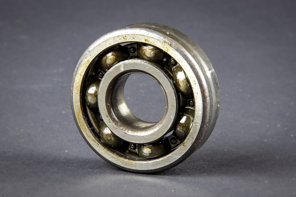
Take an illustrative case, chosen to show the method rather than to represent any particular machine: a 6208 deep groove ball bearing, the size that keeps turning up in gearbox teardowns, 40 by 80 by 18 mm, with a dynamic load rating of around 32.5 kN and a static rating of around 19 kN. It supports a pulley shaft with a radial load of 3.0 kN at 1,450 rpm. With no axial load, P equals 3.0 kN, C/P is about 10.8, and cubing gives an L10 of roughly 1,270 million revolutions. Converting at 1,450 rpm gives an L10h of about 14,600 hours. Now add an axial load of 1.0 kN from a thermal thrust or a poorly located shaft. Fa/Fr is 0.33, above the e value of roughly 0.26 to 0.28, so P becomes 0.56 × 3.0 plus a Y of around 1.7 × 1.0, about 3.4 kN. Life falls to roughly 10,000 hours, a loss of about 30 per cent from one kilonewton of thrust. For variants such as the SKF E2.6208-2Z/C3, use that exact product’s C value.
Reliability factor a1 and the meaning of 90 per cent
The 90 per cent in L10 is a reliability statement, not a promise about any single bearing. It means that, under the stated conditions, one bearing in ten is expected to show fatigue before the calculated life and nine in ten will run longer. Fatigue life follows a Weibull distribution with wide scatter, and the median life of a population is commonly quoted as roughly four to five times L10. That is exactly why L10h is neither a mean nor an expected life, and why it should never be used as a fixed replacement interval. When higher reliability is required, ISO 281 introduces the life modification factor a1. At 90 per cent reliability a1 is 1; at 95 per cent it is 0.64, at 98 per cent 0.37 and at 99 per cent 0.25. In the illustrative 6208 case without thrust, demanding 99 per cent reliability cuts the 14,600-hour figure to about 3,650 hours. For a plant running forty identical pumps, that is the difference between an occasional unplanned stop and a recurring one.
The aISO factor: lubrication, contamination and fatigue load limit
The modified rating life, Lnm = a1 × aISO × L10, brings operating conditions into the calculation. It is derived from three inputs. The first is the viscosity ratio kappa, the actual kinematic viscosity of the lubricant at operating temperature divided by the reference viscosity needed to separate the surfaces at that speed and bearing size. Below a kappa of 1 the film is marginal and aISO falls quickly; between about 1 and 4 the benefit grows, and above 4 the standard gives no further credit. The second is the contamination factor eC, which ranges from 1 for extremely clean conditions down towards zero for very severe contamination, because over-rolled particles dent raceways and start fatigue. The third is the ratio of the fatigue load limit Pu to the load P. Because aISO is capped at 50, a clean, well lubricated, lightly loaded bearing can show a very large modified life, while the same bearing in a dusty quarry with a thin lubricant can fall well below its basic L10. This is where relubrication intervals and contamination control feed straight into the number.
What L10h cannot tell you before you order
Even the full modified calculation describes only one failure mode, subsurface rolling contact fatigue, under assumed steady conditions. It does not see the installation: a bearing hammered onto its seat, a housing bore out of round, or a shaft shoulder that does not square the inner ring will fail long before fatigue becomes relevant. It does not see contamination events, such as a damaged seal or one relubrication with the wrong grease, because eC describes an average condition rather than an incident. It does not model seal wear, which is often the real life limit of a sealed bearing, nor grease life, which in many small sealed bearings running on their original fill is shorter than the fatigue life. It ignores electrical erosion from inverters, false brinelling at standstill, storage corrosion and excessive misalignment. In service, most bearings are removed for one of these reasons rather than for classical fatigue, which is why a long L10h is a necessary condition for reliability and never a sufficient one.
So what should a buyer or engineer do with the figure before placing an order? Use L10h as a comparison and screening tool. It tells you whether a proposed size has adequate fatigue margin for the duty, whether an alternative brand or design with a different C value changes that margin, and how sensitive the result is to the load and speed assumptions. Design targets for industrial machinery are commonly set at around 20,000 to 30,000 hours for equipment working a single shift and 50,000 hours or more for continuous operation, but those targets only mean something when the loads behind them are realistic. Check P before C, apply a1 where downtime is expensive, use aISO honestly rather than optimistically, and then spend equal effort on fits, alignment, sealing and lubrication. Manufacturers such as SKF publish calculators that apply the method consistently; the judgement about the inputs remains yours.
Unsure whether your bearing size really has enough life margin? Our team supports engineers and buyers in checking ISO 281 life calculations, load assumptions and alternative sizes before the order is placed. Book a free consultation.
Image credits: “Ermüdungsschaden am Außenring eines Wälzlagers” by GfMmbH (CC BY-SA 4.0); “2020-12-14-Rillenkugellager-0747” by Superbass (CC BY-SA 4.0), via Wikimedia Commons.