
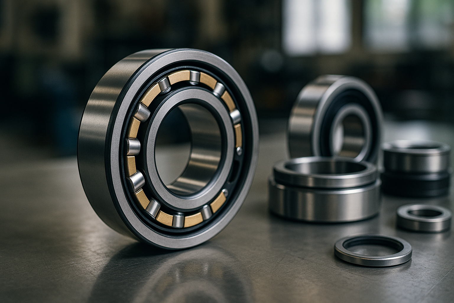
A gearbox rebuild goes back together on a Thursday, runs for two days, and comes back with the non-drive end bearing running forty degrees hotter than the drive end. The fitter has replaced an NU with an NJ because that is what the stores had in stock and the dimensions were identical. They are not interchangeable, and the difference between the two cylindrical roller bearing types is the single most misunderstood point at a parts counter. Everything about these bearings — bore, outside diameter, width, load rating, even the cage — can match perfectly while the rib arrangement makes one part correct and the other a guaranteed failure. The prefixes are not variants of a theme; they describe fundamentally different jobs within a shaft arrangement, and reading them correctly takes about two minutes once the underlying logic is clear.
What the rib arrangement is actually doing
A cylindrical roller bearing carries radial load through line contact between roller and raceway, which is why it outperforms a ball bearing of the same envelope by a wide margin on load capacity and stiffness. Axial load is a different matter entirely. The rollers can only push sideways against a rib, a raised shoulder machined on one of the rings, and sliding contact between a roller end face and a rib is a poor bearing surface: it generates heat, it needs generous lubrication, and it has a small fraction of the capacity of the radial path. So the designation letters are simply a map of where the ribs are. Two ribs on the outer ring and none on the inner means the inner ring can slide freely, giving no axial capacity at all. Two on the outer plus one on the inner means the rollers can push one way but not the other. Add a loose ring to complete the set and you have location in both directions. Once you read the prefix as a rib diagram rather than a product code, the selection becomes obvious.
NU is the pure floating position
An NU has both ribs on the outer ring and a plain, rib-free inner ring, which means the inner ring and the roller assembly can move axially relative to each other without restriction. That is not a limitation to be tolerated; it is the whole point. In almost any shaft longer than a few hundred millimetres, thermal growth between a cold morning start and a hot afternoon running condition is measurable in tenths of a millimetre, and something has to absorb it. If both bearing positions locate the shaft axially, that growth turns directly into axial load with nowhere to go, which is exactly what produced the forty-degree temperature rise in the opening example. An NU in the non-located position lets the shaft grow while still carrying full radial load, and it does so without relying on an outer ring sliding in its housing bore, which is the alternative and less reliable method. A reference such as the NU308-E-XL-M1-C3 is the standard answer for a 40 mm floating position in general machinery.
NJ locates in one direction, and that is often exactly what you want
An NJ adds a single rib to the inner ring, so the rollers can transmit axial load in one direction only. This is more useful than it sounds, because a great many machines produce axial thrust that only ever acts one way: a single-helical gear under a known torque direction, a fan with a fixed airflow direction, a pump with a defined hydraulic thrust. Where the direction is genuinely fixed, an NJ handles it without adding a separate thrust bearing, and the arrangement stays compact. The danger is the case where the thrust reverses — during run-down, during a reverse jog, or when a helical gear set is driven backwards — because then the rollers simply climb off the rib and the shaft moves, potentially far enough to unload a coupling or contact a seal. A common and robust arrangement pairs two NJ bearings facing opposite directions at the two ends of a shaft, which locates the shaft in both directions while still leaving a controlled axial gap for thermal growth. An NJ 2308 ECJ/C3 in a double-row-width envelope shows how much radial capacity that arrangement can carry.
NUP and the HJ ring: locating without a second bearing
An NUP is an NJ with a second inner-ring rib supplied as a separate loose ring that is fitted after the bearing is on the shaft. The result is a bearing that locates the shaft in both directions on its own, which makes it the standard choice for the located position in a gearbox or an electric motor where a separate thrust bearing would not fit. The same effect can be achieved by fitting an HJ angle ring to an NJ, and the two approaches are functionally equivalent, though the NUP is neater because the loose ring is supplied matched to the bearing. The critical practical point is that axial capacity in both cases remains modest — a small fraction of the radial rating — and it should be treated as a location function rather than a thrust bearing. If the application produces genuine sustained axial load, put in an arrangement designed for it rather than asking a rib to do the work. Sizing that properly starts from the same load-direction analysis described in our piece on shaft and housing fits.
N and NN: when the ribs live on the inner ring
An N reverses the NU arrangement: both ribs sit on the inner ring and the outer ring is plain, so the outer ring is free to move axially within its housing bore. This is the right choice when the housing, rather than the shaft, is the part that will grow or when the outer ring needs to slide as part of the machine’s normal function. It is much less common in general industry than NU, and the practical reason is that the sliding surface is now the outer ring against a cast housing bore rather than an internal ground steel surface, which is a worse bearing surface and a worse wear proposition. Double-row variants carrying the NN and NNU prefixes follow the same convention and appear mainly in machine tool spindles, where their radial stiffness and the ability to adjust clearance on a tapered bore matter more than anything else. The broader family is laid out in our complete guide to cylindrical roller bearings.
Floating the ring or floating the bearing
There are two ways to build a floating position, and choosing between them is a real engineering decision rather than a preference. The first is to use an NU or N and let the sliding happen internally, between rollers and a plain raceway, on ground and lubricated steel. The second is to use a bearing that cannot float internally — a deep groove ball bearing, a spherical roller bearing — and let the outer ring slide in an H7 housing bore. The internal method is far more reliable, because the sliding surface is designed for it and because the friction force needed to make it move is small. The external method depends on a machined cast iron bore staying clean, unfretted and undamaged for the life of the machine, and fretting corrosion at that interface is one of the most common causes of a floating position quietly becoming a located one. Where shaft lengths are significant or duty is heavy, a single row cylindrical roller bearing in the floating position is worth the extra cost for this reason alone.
Mounting order and the mistake that scores a new bearing on day one
Because the inner ring and the roller assembly of an NU or NJ separate completely, these bearings are mounted in two stages: the inner ring is heated and fitted to the shaft, the outer ring and roller set go into the housing, and the two halves are brought together during final assembly. That last step is where damage occurs. If the shaft is offered up misaligned, the roller ends drag across the inner ring raceway and leave axial scoring that will become a noise complaint within weeks. The remedy is mechanical rather than skilful: support the shaft so it enters square, rotate the outer assembly slowly by hand as the rings engage so the rollers find their own position, and never use axial force to overcome resistance. It is also worth confirming that the separable halves belong together, because roller sets are matched to their outer rings and mixing two bearings of the same reference is a real failure mode in a busy workshop. The related practice for paired mounts is covered in our notes on setting preload without wrecking the seat.
The selection rule that comes out of all this fits in one sentence: decide which position locates the shaft and which position lets it grow, then pick the prefix that matches. Non-located position, no axial capacity wanted, use NU. Located position on its own, use NUP or NJ with an HJ ring. Thrust in one known direction only, use NJ. Housing moves instead of the shaft, use N. Everything else — clearance class, cage material, the E and XL designations that mark uprated internal geometry — sits downstream of that decision and can be chosen from the catalogue once the arrangement is settled. Getting it backwards produces a bearing that is dimensionally perfect, correctly fitted, properly lubricated, and running forty degrees too hot.
Not sure which prefix your arrangement needs? Our team supports European workshops and OEMs with cylindrical roller selection, located and floating position advice and same-reference cross-brand alternatives. Book a free consultation.