
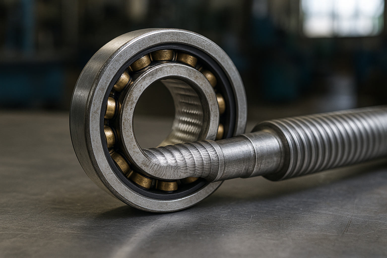
A 22 kW pump motor on a variable speed drive runs for fourteen months and then starts to whine. The bearing comes out and the outer ring raceway carries a pattern of fine, evenly spaced transverse lines, like the surface of a vinyl record, running the full width of the load zone. Nothing in the mechanical installation explains it: alignment is good, the fit is correct, the grease is clean and the right quantity. The cause is electrical, and the pattern is the classic signature of shaft currents in electric motors discharging through the bearing. This failure mode barely existed before inverter drives became the default, and it has been quietly responsible for a large share of premature motor bearing replacements ever since. The mechanism is well understood and the countermeasures are effective, but they have to be chosen against the specific current path involved, and choosing the wrong one costs money without fixing anything.
Where the voltage comes from in the first place
A sinusoidal supply produces a magnetic field that is close to symmetrical, and the residual voltage induced along the rotor shaft is small. An inverter does not produce a sinusoid. It produces a train of steep-sided pulses, and the sum of the three phase voltages at any instant is not zero but a rapidly switching common mode voltage referenced to earth. That common mode voltage appears across the stray capacitances inside the motor: winding to rotor, winding to frame, rotor to frame. The rotor therefore sits at a potential that steps up and down thousands of times per second, and the only path from rotor to earthed frame runs through the bearings. Two distinct phenomena follow. Capacitive discharge occurs when the rotor voltage exceeds the dielectric strength of the lubricant film and punches through it. Circulating current occurs at higher powers, where the high frequency flux around the stator induces a shaft-end-to-shaft-end voltage that drives a current loop through both bearings and the frame. The two need different remedies, which is the first thing to establish.
Frosting, pitting and fluting are three stages of one process
Each discharge event is a miniature electrical discharge machining operation. Current crosses at the narrow point where a rolling element approaches the raceway, local temperature at the contact spike far beyond the melting point of the steel for a few microseconds, and a crater a few microns across is left behind with a rim of resolidified metal. One crater is irrelevant. Millions of them produce a matt, grey, slightly rough surface that is called frosting, and at that stage the bearing still runs acceptably though it is noisier than new. As the surface roughens, the lubricant film becomes less able to separate the surfaces, discharge becomes easier, and the process accelerates. Fluting appears later and is a resonance effect rather than a direct electrical one: the roughened surface excites a vibration in the rolling element passage, and the discharge preferentially occurs at the vibration antinodes, machining the regular washboard pattern that gives the failure its name. By the time fluting is visible the bearing is beyond saving, and the noise complaint that brought it to attention is generated by the flutes rather than by the original damage.
Why the grease film is the whole battleground
Everything in this failure mode turns on whether the lubricant film is thick enough and insulating enough to withstand the rotor voltage. That leads to a counterintuitive and important consequence: the risk is highest at low speed and at standstill-to-running transitions, not at full speed. A thick elastohydrodynamic film at rated speed can hold off several volts; the same bearing at ten percent speed has a film of a fraction of that thickness and breaks down at well under a volt. Variable speed applications that spend time at low speed — cooling tower fans on temperature control, pumps on flow control, conveyor drives that creep — are therefore far more exposed than a motor run at fixed high speed on an inverter for soft-start purposes only. Grease composition matters too, and not in the direction people assume: conductive greases are marketed for this problem but tend to produce continuous low-level current flow and accelerated additive breakdown rather than protection. The more dependable route is to keep a clean, correctly sized standard grease charge and to attack the current path itself. The general principles of matching lubricant to duty are covered in our piece on choosing between grease and oil on a mid-speed shaft.
Reading the damage: electrical erosion versus mechanical damage
Distinguishing electrical damage from ordinary wear is straightforward once you know what to look for, and getting it right prevents an expensive and useless chase after alignment or fit problems. Electrical erosion is confined to the load zone, is uniform in appearance across that zone, and affects both raceway and rolling elements — the balls will be frosted too, which is the clearest single indicator, because mechanical overload does not produce that uniform matt finish on the rolling elements. Fluting lines run transverse to the direction of rotation, are regularly spaced, and have rounded rather than sharp edges under magnification. False brinelling from transport vibration, by contrast, produces marks at ball pitch spacing that are polished rather than matt and that do not appear on the balls. True brinelling from impact produces isolated indentations with raised rims. Contamination damage produces random scattered dents of varying size. Grease should also be inspected: electrically damaged bearings typically show darkened grease with fine metallic particles in suspension, well before any bulk discolouration from heat. Building this into a standard inspection routine costs very little and is a natural extension of a vibration monitoring route.
Insulated and hybrid bearings, and where each belongs
The two bearing-side countermeasures work quite differently. An insulated bearing carries an oxide coating on the outer ring outside diameter or bore, which places a capacitor and a high resistance in the current path at that ring. It is highly effective against circulating currents, because it breaks the loop through the frame, and it is the standard specification on larger motors for that reason. Its weakness is that it is still a capacitor: at the switching frequencies involved, high frequency current can still pass, so an insulated bearing alone is not a complete answer to capacitive discharge. A hybrid bearing with ceramic rolling elements is different in kind, because the insulating element sits directly in the current path at the contact and is a genuine dielectric rather than a coating. Hybrids handle both mechanisms and additionally run cooler and faster, which is why they dominate in high-speed and traction applications. The cost differential is real, and the judgement of when it is repaid is set out in our note on when to reach for a hybrid bearing. In a drive-end and non-drive-end pair, insulating only one position is standard practice for circulating current, since breaking the loop once is sufficient, but capacitive discharge requires protection at the discharging end specifically.
Shaft grounding rings are not maintenance-free
A shaft grounding ring gives the rotor a deliberate low-impedance path to the frame through conductive fibres or a brush, so that current takes that route rather than the bearing. Properly specified and properly installed, it is an effective and comparatively cheap countermeasure, and it has the advantage of being retrofittable without changing the bearings. The caveats matter. The ring has to be mounted concentric with the shaft and on a clean, unpainted, unplated shaft surface, because contact resistance is what determines whether the current actually prefers that path. The fibres wear and become contaminated by grease, dust and coolant mist, so in a dirty environment the ring can quietly stop working while remaining visibly present, which is the worst possible outcome: the motor appears protected and is not. Any installation using grounding rings needs them on the inspection schedule with a defined check — a resistance measurement shaft to frame, not a visual glance — and in a wet or dusty plant that check belongs at every service interval rather than annually.
Cable, filter and installation measures that work at source
The cheapest interventions happen at installation and are routinely skipped. Symmetrical shielded motor cable with a 360 degree shield termination at both ends gives the high frequency common mode current a low-impedance return path back to the drive, which dramatically reduces the current available to find its way through the bearings. A pigtailed shield connection, which is still common, is close to useless at these frequencies because the inductance of the pigtail defeats the purpose. Output filters on the drive — common mode chokes, dV/dt filters or full sine filters — attack the source directly by softening the pulse edges, and a sine filter effectively eliminates the problem at the cost of price, size and some efficiency. Bonding matters as much as any component: a proper high frequency bond between motor frame and driven machine frame stops the current from routing through the coupling and the driven equipment’s bearings, which is a failure mode that catches people out when the motor is protected and the pump fails instead. These measures are cumulative rather than alternatives.
Choosing a strategy for a fleet rather than for one motor
For a plant with dozens of inverter-driven motors, treating each failure individually is the expensive path. A workable policy bands the fleet by risk. Motors below roughly 100 kW on inverters are dominated by capacitive discharge and are best addressed with grounding rings or, where downtime is costly, hybrid or insulated bearings at the non-drive end. Motors above that threshold, where the frame is large enough for meaningful circulating current, get an insulated non-drive-end bearing as standard specification at purchase, which costs very little when ordered with the motor and a great deal when retrofitted. Anything running extended periods at low speed moves up a band regardless of power. Alongside that, the stores policy should reflect it: holding a standard 6308-2ZTN9/C3 for general replacement is sensible, but replacing a failed motor bearing like for like without asking why it failed simply resets a clock that will run out again in fourteen months. The wider selection question for inverter and traction duty is explored in our piece on why EV motors need a different bearing, and the same physics applies to industrial drives. A plain deep groove ball bearing is the right part in the right context and the wrong one in the wrong context.
What makes this failure mode frustrating is that every mechanical check passes. Alignment is within tolerance, the fit is correct, the grease is clean, the load is well within rating, and the bearing still fails at a fraction of its calculated life. The diagnostic discipline that resolves it is to look at the rolling elements under magnification before anything else, because a matt frosted ball is conclusive in a way that no amount of vibration data is. Once electrical erosion is confirmed, the question becomes which mechanism and therefore which countermeasure, and that is answered by motor size, speed profile and how the installation was cabled rather than by anything visible in the bearing itself. Plants that record the answer once and apply it as a purchasing standard stop seeing the failure; plants that fit a new bearing and move on see it again next year.
Losing motor bearings on a fourteen-month cycle? Our team supports European plants and motor rewinders with insulated and hybrid bearing options, clearance classes and drive-end specification for inverter duty. Book a free consultation.