
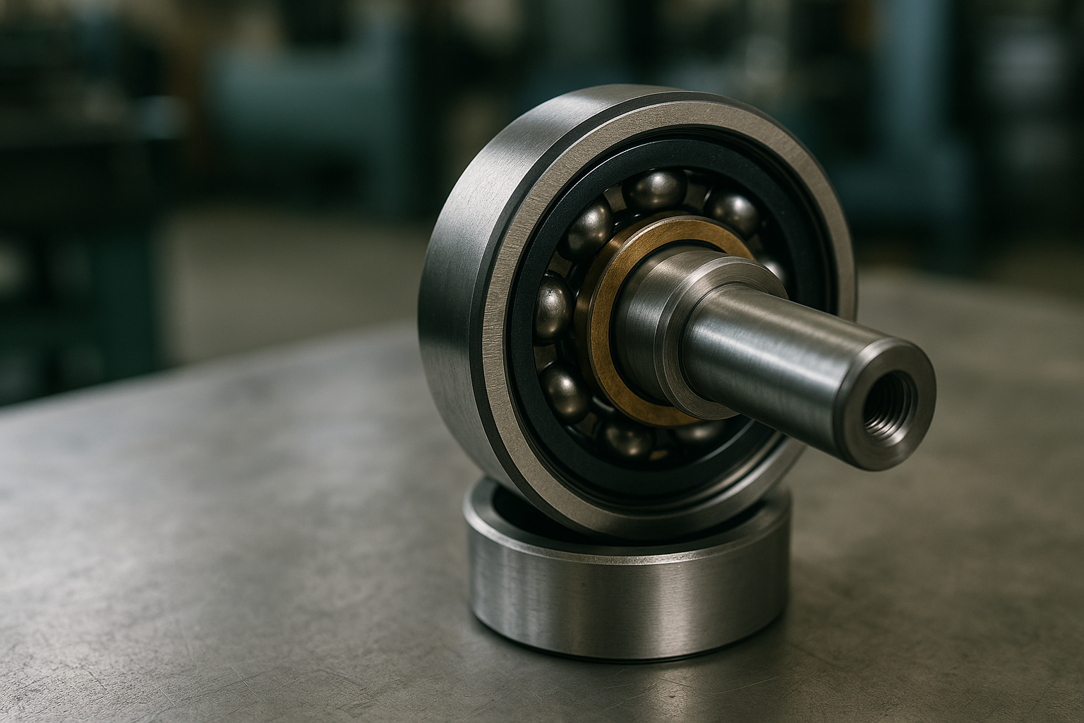
A fan shaft comes back into the workshop for the third time in a year, and the bearing on the drive end is polished bright on the bore with a faint spiral scoring pattern that nobody can explain. The bearing itself is the correct reference, correctly greased, correctly aligned. What is wrong is the fit: the shaft seat has worn a few microns undersize, the inner ring is creeping, and every rotation grinds a little more steel off the seat. Getting shaft and housing fits right is the least glamorous decision in a bearing installation and the one that most reliably decides whether the part reaches its calculated life or a fraction of it. The catalogue tables that govern this look intimidating, but they collapse into a small number of physical questions, and once those are answered the letter-and-number codes follow almost mechanically.
Rotating load, stationary load, and why the distinction comes first
Before any tolerance code means anything, you have to establish which ring sees a load that moves around its circumference and which sees a load fixed at one point. On an ordinary electric motor or fan, the shaft turns and the load — belt pull, rotor weight, impeller reaction — points in a fixed direction in space. The inner ring therefore presents every point of its raceway to the load in turn, which is a rotating load, while the outer ring is loaded permanently in one zone, a stationary load. The rule that follows is simple and almost never violated in good practice: the ring carrying the rotating load gets an interference fit, and the ring carrying the stationary load gets a looser fit, usually a transition or clearance fit. The reason is creep. A ring under rotating load will slowly walk around its seat unless it is gripped, because the contact patch travels and drags the ring with it. A ring under stationary load has no such tendency and can be left free enough to move axially. Reverse the two and you get the polished, scored shaft seat described above.
What k5, m6 and n6 actually mean at the shaft
Shaft tolerance codes use a lowercase letter for the position of the tolerance band relative to nominal and a number for its width. Lowercase letters from j upward sit above the nominal line, which is what creates interference against a bearing bore that is itself machined to a negative tolerance. In practice k5 and m6 cover the overwhelming majority of industrial cases. A k5 shaft gives light interference suited to normal loads on ball bearings and small roller bearings, while m6 gives more grip for heavier loads or where shock is present, and n6 is reserved for genuinely heavy or shock-loaded roller bearings. The number matters as much as the letter: a grade 5 band is roughly two thirds the width of a grade 6, so k5 delivers a much more predictable interference than k6 across a batch of shafts. This is why a manufacturer will specify k5 for a precision application and accept k6 for general machinery — not because the average fit differs greatly, but because the spread does. If the code notation itself is unfamiliar territory, our guide to reading a catalogue tolerance code covers the arithmetic in detail.
H7 in the housing and the case for letting a ring float
Housing bores use uppercase letters, and H7 is the workhorse. It places the tolerance band entirely above nominal, giving a small clearance against the bearing outer diameter, which is exactly what you want when the outer ring carries a stationary load and needs to slide axially to accommodate shaft expansion. In a two-bearing arrangement, one position is located and one floats, and the floating position almost always relies on an H7 bore to let the outer ring shift a fraction of a millimetre as the shaft grows with temperature. Tighten that bore to K7 or M7 and the shaft becomes axially trapped between two located bearings, which loads both of them in a direction the designer never intended and shows up as high running temperature and short life on the non-drive end. Where the housing rotates instead of the shaft — a wheel hub, an idler pulley, a tensioner — the logic inverts completely: the outer ring now carries the rotating load and needs the interference, typically N7 or P7, while the shaft can run to h6 or g6. A bearing supplied for a housing unit often assumes this inversion in its own tolerance specification.
Interference eats internal clearance, and that is why C3 exists
An interference fit does not simply hold the ring; it expands it. Press an inner ring onto a solid shaft with 20 microns of interference and a substantial share of that expansion — commonly around eighty percent for a solid steel shaft — transfers to the raceway, reducing the radial internal clearance by the same amount. Start with a normal clearance bearing, apply a firm m6 fit, and you can consume most of the residual clearance before the machine has run for a second. Add thermal expansion of the inner ring in service and the bearing can go into preload, which drives temperature up, which expands the ring further, which is how a perfectly good bearing cooks itself in an afternoon. This is the entire reason the C3 clearance class exists as a stock item rather than a specialty: it gives the assembly somewhere to go. Any time you are specifying a tighter-than-normal fit, a hollow shaft, an aluminium housing or an application running above about seventy degrees, C3 should be the default rather than the exception. The mechanics of the clearance classes themselves are set out in our explainer on bearing internal clearance.
Temperature difference across the bearing changes the fit you chose
Catalogue fit tables assume the bearing runs at a modest and fairly uniform temperature. Real machines rarely oblige. In a gearbox, the inner ring sits on a shaft warmed by oil churn and gear mesh while the outer ring sits in a housing being cooled by ambient air, and a fifteen to twenty degree difference across the bearing is entirely normal. Steel expands roughly eleven microns per metre per degree, so on a 90 mm bore that difference is worth something like fifteen to twenty microns of lost clearance on its own, before the fit is even counted. In a hot application — a kiln fan, a dryer roll, a calender — the differential can be far larger and the direction of the problem changes: the shaft may grow enough that a k5 fit becomes effectively an n6 fit at operating temperature. The correct response is to work the numbers at operating temperature rather than at twenty degrees, choose clearance class accordingly, and accept that a fit which feels loose in the workshop may be exactly right once the machine is hot. A cylindrical roller bearing in the floating position tolerates this far better than a ball bearing, which is why designers reach for one on hot shafts.
Thin housings, light alloy and the assumptions the tables make
The standard fit tables assume a steel or cast iron housing thick enough to be effectively rigid. Two increasingly common situations break that assumption. The first is a thin-walled steel housing, typical of fabricated equipment and pressed-steel units, where the bore simply deflects under an interference fit instead of gripping, so the nominal interference does not produce the nominal contact pressure. The second is an aluminium housing, where the thermal expansion coefficient is roughly twice that of the bearing steel: a bore that is a snug H7 at room temperature opens up appreciably at eighty degrees, and an outer ring that was adequately supported in the morning starts creeping by mid-afternoon. Both cases call for a tighter nominal fit than the table suggests, and in aluminium the usual answer is to move one grade tighter and accept that the cold assembly will need heating or a press. Ignore this and you get bore wear in the housing, which is far more expensive to repair than a worn shaft seat because there is no simple sleeve remedy.
Measuring the seat rather than trusting the drawing
Most fit problems in maintenance work are not design errors; they are dimensional drift on a seat that has been in service for years. A shaft seat that has carried a creeping inner ring will be undersize and often out of round, and a housing bore that has fretted will be oversize and bell-mouthed. Neither condition is visible, and both are quick to measure: a micrometer at three axial positions and three angular positions on the shaft, a bore gauge doing the same in the housing, and a note of the actual numbers rather than a verdict. Compare those against the bearing’s own bore and outside diameter, measured rather than assumed, because bearing tolerances have a spread too and a part at the bottom of its band on a shaft at the top of its band gives a very different interference from the nominal calculation. Ten minutes with a micrometer at this stage prevents the repeat failure that costs a day. Where the seat is genuinely worn, a repair sleeve or metal spray and regrind is a legitimate answer; running a new bearing onto a worn seat is not, and the technique for getting a ring off without wrecking the seat further is covered in our notes on freeing a locked adaptor sleeve.
When to stop fighting the fit and use a sleeve
There is a class of application where machining a precision seat is simply not worth it: long plain shafts on conveyors, agitators, fans and agricultural equipment, where the shaft is drawn bar rather than ground and the bearing is a self-aligning or spherical type. Here the adapter sleeve exists precisely to sidestep the fit problem. A tapered sleeve with a lock nut clamps a spherical roller bearing onto a shaft of ordinary commercial tolerance, and the interference is set by how far the ring is driven up the taper rather than by the shaft diameter. The trade-off is that you now control the fit by clearance reduction measurement or by a defined axial drive-up distance, and getting that wrong preloads the bearing just as effectively as an over-tight press fit would. A reference such as the 22213-K-M-C3, with its tapered bore and C3 clearance, is built for exactly this method, and the C3 designation is there because the mounting process is expected to consume clearance.
The pattern behind all of this is that a fit is not a property of the bearing or of the shaft but of the assembly at operating temperature under its actual load pattern. Establish which ring rotates relative to the load, pick interference for that ring and freedom for the other, then check whether temperature, housing material or shaft construction will move the numbers once the machine is running. Where the answer is yes, buy the clearance back with a C3 bearing rather than loosening the fit, because a loose fit under rotating load fails progressively and expensively while extra internal clearance costs nothing. Machines that eat bearings on one position and not the other are almost always telling you something about fits rather than about the bearings, and the diagnosis usually takes a micrometer rather than a vibration analyser.
Worn seat or the wrong clearance class? Our team supports European workshops and OEMs with fit selection, clearance classes and tapered-bore alternatives for shafts that will not hold a seat. Book a free consultation.