
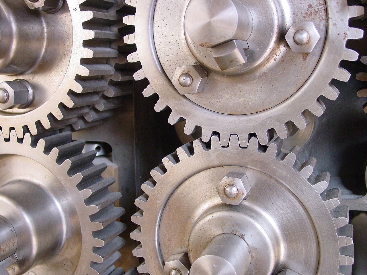
When a maintenance fitter rings the parts counter asking whether he can replace one of his spur gears with hub with a cheaper plate gear, the honest answer is that it depends on what will hold the gear to the shaft. In the case on the phone, the original gear on a packaging-line transfer drive had worn its keyway into a bell mouth after years of reversing duty, the only replacement on the shelf with the right module and tooth count was a hubless plate, and the machine had to run again before the night shift. The tooth geometry of the two parts was identical, so the mesh would have been fine. What differed was the length of bore available to carry torque, the room for a set screw and the way the gear would be located along the shaft. That difference is the subject of this article, because choosing between a hubbed gear and a plate gear is a decision about the shaft connection far more than about the teeth themselves.
Module, basic rack and what makes two gears mesh
Before the hub question, it is worth confirming that the gears will mesh at all, and in Europe that conversation starts with the module. The module m is the reference diameter divided by the number of teeth, expressed in millimetres, so a module 2.5 gear with 65 teeth has a reference diameter of 162.5 mm and, with the standard addendum, a tip diameter of m(z+2), or 167.5 mm. Stock spur gears are cut to the basic rack profile defined in DIN 867 and ISO 53, with a 20° pressure angle, an addendum of 1.0 m and a dedendum of 1.25 m. Two gears mesh correctly only when module and pressure angle match; tooth count, face width and hub style can differ freely. This is why a part such as the spur gear module 2.5 Z65 can pair with a 15-tooth pinion of the same module from another batch. Imperial diametral-pitch gears and older 14.5° profiles look similar on the bench but will not run quietly against a metric 20° gear, so check the marking first.
Pilot bores, keyways and set screws
Most catalogue spur gears leave the factory with a pilot bore, a deliberately undersized hole that lets the user machine the final fit. Usual practice is to bore to H7 for a k6 or j6 shaft, then broach a keyway to DIN 6885-1 sized to the shaft, for example a 10 x 8 key on a shaft between 30 and 38 mm. A set screw, normally placed over the key, stops the gear walking along the shaft and takes up the small clearance between key and keyway. The reasoning behind those fit choices is the same one covered in our note on the four fits every mechanical designer keeps re-deriving. The critical point when re-boring is concentricity: if the gear is chucked on its tip diameter rather than located on the pilot bore or a faced datum, any runout appears directly as transmission error, noise and uneven tooth wear. Workshops that re-bore regularly indicate the bore and the face before cutting, because once the bore has been enlarged off-centre the error cannot be corrected.
What the hub actually buys you
A hub is extra axial length concentrated around the bore, and that length is what carries torque through a keyed joint. The surface pressure on a key flank is proportional to the torque divided by the shaft diameter, the bearing height of the key and its effective length, so doubling the engaged length roughly halves the pressure. On a plate gear with a 25 mm face width and a 35 mm shaft, key engagement is limited to that face width, which may be adequate for a steady drive and marginal for a reversing or shock-loaded one. The hub also provides a radial wall thick enough to take a threaded set screw without the thread breaking towards the tooth root, and a face against which a collar or spacer can locate. Many designers work to a hub length of at least the shaft diameter for keyed joints in general machinery, and more under shock. Our spur gears with hub follow this logic, with hub length and diameter scaled to the largest recommended bore for each size.
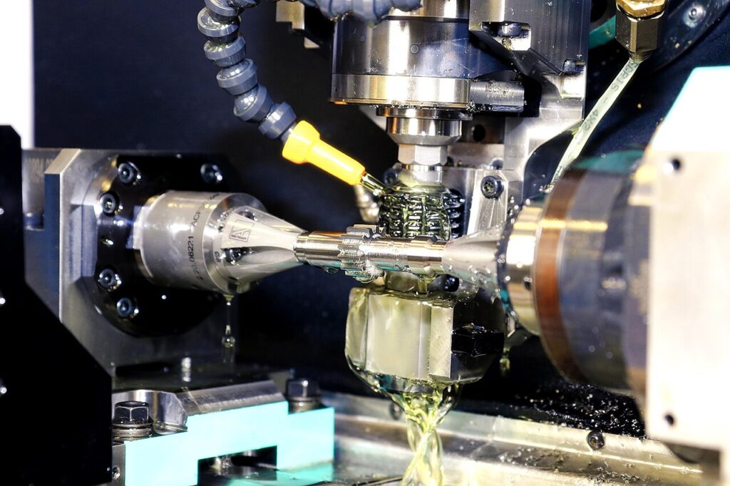
Plate gears and separate locking elements
A gear without a hub is not a lesser part; it is a part designed to be fixed by something else. Plate gears are commonly bolted to a flange, welded to a fabricated hub or clamped directly to the shaft with a keyless locking element. Spur gears without hub are the natural choice where axial space is tight, where the gear must sit close to a bearing housing, or where it will be fixed to another rotating part. Bolted to a flange with a spigot, a plate gear transfers torque through friction under the clamped faces while the spigot provides concentricity, so the bore is no longer the critical feature. With a shaft clamping element, tapered rings generate radial pressure on both the shaft and the gear bore, giving a joint with no keyway and no rotational play. The condition is that the gear body must resist the hoop stress the element induces; the element catalogue gives a minimum hub outside diameter for each size, and a thin plate gear with a large bore often fails that check.
When a hubless gear and a locking element beat a hub
The keyed hub remains the cheapest reliable connection for steady drives that turn in one direction, but there are clear cases where a plate gear plus a separate locking element is the better engineering answer. Reversing drives and indexing tables fret keyways: every reversal takes up the clearance between key and slot, and after enough cycles the keyway is ovalised and the gear rocks on the shaft. A keyless element removes that clearance entirely. Positioning drives, where the angular relationship between two gears must be set during assembly, also benefit, because the gear can be rotated to any angle before clamping, whereas a keyway fixes it. Repairs are another case: a shaft with a damaged keyway can often be saved by fitting the gear on an undamaged section with a clamping element, avoiding a new shaft. Taper bushes sit between the two approaches, giving a standard bore range and quick removal, although they still use a key and are far more common on sprockets and pulleys than on gear meshes.
Face width, material and load capacity
Face width is the second number after module that determines how much torque a stock gear will carry. Catalogue spur gears are typically produced with face widths in the region of ten times the module, so around 25 mm for module 2.5, and widening the face raises load capacity roughly in proportion, provided the shafts are stiff and aligned enough for the full width to make contact. Material is the third lever. Unhardened C45 steel is the standard for general-purpose stock gears because it machines well, re-bores easily and is tough enough for moderate loads; induction-hardened teeth raise surface durability considerably where pitting is the limit, while the bore and hub stay soft enough for machining. Cast iron runs quietly, and polyacetal or polyamide gears serve light, quiet drives where lubrication is impractical. A full rating calculation follows ISO 6336, but for selecting a stock gear the manufacturer’s torque table at the actual speed is usually sufficient.
Centre distance, backlash and bearing support
Two stock gears mesh at a theoretical centre distance of m(z1 + z2)/2, so a module 2.5 pair of 65 and 15 teeth runs at 100 mm. Stock gears are cut with a tooth thickness allowance that creates a small backlash at that distance. As a working approximation, each 0.1 mm increase in centre distance on a 20° gear adds about 0.07 mm of circumferential backlash, because the change equals roughly twice the centre-distance error times the tangent of the pressure angle. Too tight is worse than too loose: a mesh without backlash heats up, runs noisily and loads the shaft bearings with a radial force they were never sized for. Bearing support matters as much as the gear, which is why worn bearings appear in so many of the cases described in why the 6208 keeps showing up in gearbox teardowns: once a bearing lets the shaft deflect, the mesh moves off its design centre distance and tooth wear accelerates.
Put together, the choice is straightforward once the shaft connection is treated as the design decision. Choose a hubbed gear when the drive turns mostly in one direction, the shaft is keyed, axial space is available and the gear will be re-bored in the workshop; the hub gives key length, set-screw room and an easy datum. Choose a plate gear when it will be bolted to a flange, welded to a fabricated hub, mounted close to a housing or fixed with a keyless element on a reversing or positioning drive. In both cases check module, pressure angle, face width and centre distance first. Italian specialists such as CHIARAVALLI supply gears alongside sprockets and bushes, and our overview of the CHIARAVALLI power transmission range explains how that catalogue is organised for workshops that stock a mixed range.
Not sure whether your drive needs a hubbed gear or a plate gear with a locking element? Our team supports module, bore and keyway selection for spur gear replacements and new drives. Book a free consultation.
Image credits: “Engrenages 2” by Bachelot Pierre J-P (CC BY-SA 3.0); “Gear-hobbing-spur-gear-on-cnc-cutting-machine” by Affoltergroup (CC BY-SA 4.0), via Wikimedia Commons.