
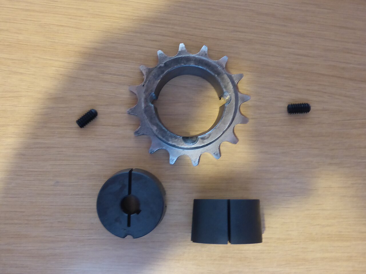
A fan pulley comes off a ventilation unit on a Monday morning, and the fitter finds that the taper lock bushes on the drive are stamped 2012 on the fan side and 1610 on the motor side, with no record of which bores were fitted. The motor has since been replaced by an IEC frame with a 28 mm shaft, the old motor bush was imperial, and the stores system lists several hundred bush variants. The good news is that the system behind those parts is one of the most rational in power transmission: a small number of standard tapers, each offered in a range of bores, fit any pulley, sprocket or hub machined for that taper. Once the designation, the bore range, the keyway standard and the screw torque are understood, the fitter can choose the right part from the code alone. This guide takes each of those points in the order in which they matter at the bench, starting with the four digits stamped on the face.
Reading the four-digit designation
The four digits of a taper bush code describe its envelope. The first two are a size code that grows with the outside diameter of the bush, and the last two give the length in tenths of an inch. A 1210 is therefore about one inch long (25.4 mm), a 1610 is also one inch long but larger in diameter, a 2012 is 1.25 inches (31.8 mm), a 2517 is 1.75 inches (44.5 mm), a 3020 is two inches (50.8 mm) and a 3525 is 2.5 inches (63.5 mm). The first two digits are not a direct dimension, so do not try to derive the outside diameter from them; the catalogue gives it, for example about 47.5 mm for a 1210 and 57 mm for a 1610 at the large end of the taper. The practical consequence is that bushes with the same first two digits but different lengths, such as 1610 and 1615, share a taper diameter but not a hub length, so the pulley or sprocket must be ordered for the full four-digit size.
Bore ranges in metric and imperial
Each bush size is offered in a series of finished bores between a minimum and a maximum set by the wall thickness of the taper. The smallest sizes start at around 10 mm, a 1610 reaches about 42 mm, a 2012 about 50 mm, a 2517 about 65 mm and a 3525 about 100 mm, with imperial bores in fractional inches covering a similar span; the exact limits for each size are in the manufacturer’s table. Our taper lock bushes are listed by size and bore. The selection logic is to pick the smallest bush whose bore range includes the shaft and whose capacity covers the drive, then confirm that the pulley or sprocket you want is offered for that bush. Metric and imperial bushes of the same designation are interchangeable in the hub because the external taper is identical; only the bore and keyway differ. That is why a Taper Lock Bush TB1610 with a 1-inch bore fits the same pulley as a 25 mm metric bush, useful in plants with mixed shafts.
Keyways to DIN 6885, BS 4235 and BS 46
Metric-bore bushes are normally broached with a keyway to DIN 6885-1, the standard that defines parallel keys on most European drawings, with BS 4235 as the British equivalent for metric keys; imperial bores follow BS 46. The key is sized to the shaft, not to the bush, so a 25 mm or 28 mm bore carries an 8 x 7 key whichever bush size it sits in. Near the maximum bore of each size, the wall between the keyway and the taper becomes too thin for a full-depth slot, so the largest bores are often supplied with a shallow keyway and a matching shallow key. Fitting a standard-height key there means it will either not seat or stand proud and score the hub. When ordering an imperial-bore part such as the Taper Lock Bush TB1210 in our range, confirm both the bore and the keyway form against the shaft, because imperial and metric keys of similar size are not interchangeable, and a key that rocks in its slot will fret the bore within weeks.
Grub screws and tightening torque
A taper bush is drawn into its hub by grub screws seated in half-holes, threaded in the hub and plain in the bush. The smaller sizes use two screws and the larger ones, from 3525 upwards, use three; the screws carry BSW threads even on metric-bore bushes, because they belong to the taper system and not to the bore. The commonly published tightening torques are about 5.6 Nm for 1008 and 1108, 20 Nm for 1210 and 1610, 30 Nm for 2012 and 50 Nm for 2517, rising to around 90 Nm for 3020 and higher for the larger sizes, and the manufacturer’s table remains the authority for any given part. These values are deliberately moderate. The shallow taper multiplies screw force into a large radial clamping pressure, so overtightening adds no useful grip; it can burst a thin hub, especially a cast-iron pulley, or damage the screw seat. Undertightening is the more common fault in practice, and it shows up as a bush that walks out of the hub and a taper surface polished by fretting.
Reading the torque rating table
Catalogues publish a torque rating for each bush size, and it is easy to misread it as a guarantee for every bore. The figure describes the capacity of the clamped taper joint, assuming correct screw torque, clean dry surfaces and a key fitted. In a real drive, the weakest link is often elsewhere. On a small bore at the bottom of the range, the shaft and key are thin, and the key surface pressure or the shaft itself may limit torque well before the taper would slip. On the largest bores, the shallow keyway reduces key capacity. Treat the published figure as the upper bound for the bush, then check key and shaft separately with the usual key pressure calculation, using the bush length as the engaged key length. Apply a service factor suited to the drive, higher for crushers and reciprocating compressors than for fans and centrifugal pumps. If the check fails, move up one bush size rather than relying on extra screw torque, which only stresses the hub without adding real capacity.
Installation and removal without damage
The fitting procedure is short and should be followed in order. Clean the taper, the bore and the hub, removing oil and preservative, because the clamp relies on friction and the tapered surfaces are assembled dry. Place the bush in the hub and line up the holes so that each threaded hub half-hole faces a plain bush half-hole, then lightly oil the screw threads and insert them. Slide the assembly onto the shaft at the required position and tighten the screws alternately and gradually to the table value. On larger sizes, tap the bush face with a sleeve or drift and re-torque, repeating until the torque holds. Grease the empty holes and check the torque again after the first hours of running. For removal, take out all the screws, insert one into the removal hole, which is threaded on the bush side and bears on the hub, and tighten until the bush releases. Never hammer the hub off; the taper releases once the jacking screw has done its job.
H and F hubs, weld-on hubs and bushed components
Taper bush hubs come in two mounting orientations. On an H-type hub the bush is inserted and tightened from the hub side; on an F-type hub it is inserted from the flange side. The choice matters on cramped motor bases, where the only reachable face may be the one away from the motor, and on fans, where the screws must be accessible from the open side of the casing. Weld-on hubs, usually designated W, let a fabricator attach a standard bush to a fan impeller, an agitator or a roller end, giving a removable shaft fit on a welded part. The same bush sizes serve a whole family of components: taper bush V-belt pulleys in SPZ, SPA, SPB and SPC profiles, simplex and duplex sprockets bored for lock bushes, and timing pulleys. Stocking a handful of bush sizes and bores therefore covers a wide variety of drives, which is the real economic advantage of the system for a plant stores department.
A taper bush is only as good as the drive around it. Once it is fitted, belt or chain tension and alignment decide whether the clamp sees steady torque or a pulsating overload, so the retension window described in our guide to V-belt tension by deflection and frequency and the pulley-face checks in our note on proper belt drive alignment apply directly to bushed pulleys. When a drive is rebuilt, pair the bush and pulley with belts from a consistent range, such as OPTIBELT wedge profiles, and record the bush size, bore and screw torque on the machine card so the next fitter does not start from a stamped number and guesswork. For workshops that want bushes, pulleys and sprockets from a single Italian source, our overview of the CHIARAVALLI power transmission range shows how one catalogue covers the whole bushed family.
Not sure which bush size and bore your shaft and torque call for? Our team supports taper bush selection, keyway checks and matching pulleys or sprockets for your drive. Book a free consultation.
Image credits: “Taper-lock-hub” by Miessen (CC0), via Wikimedia Commons.