
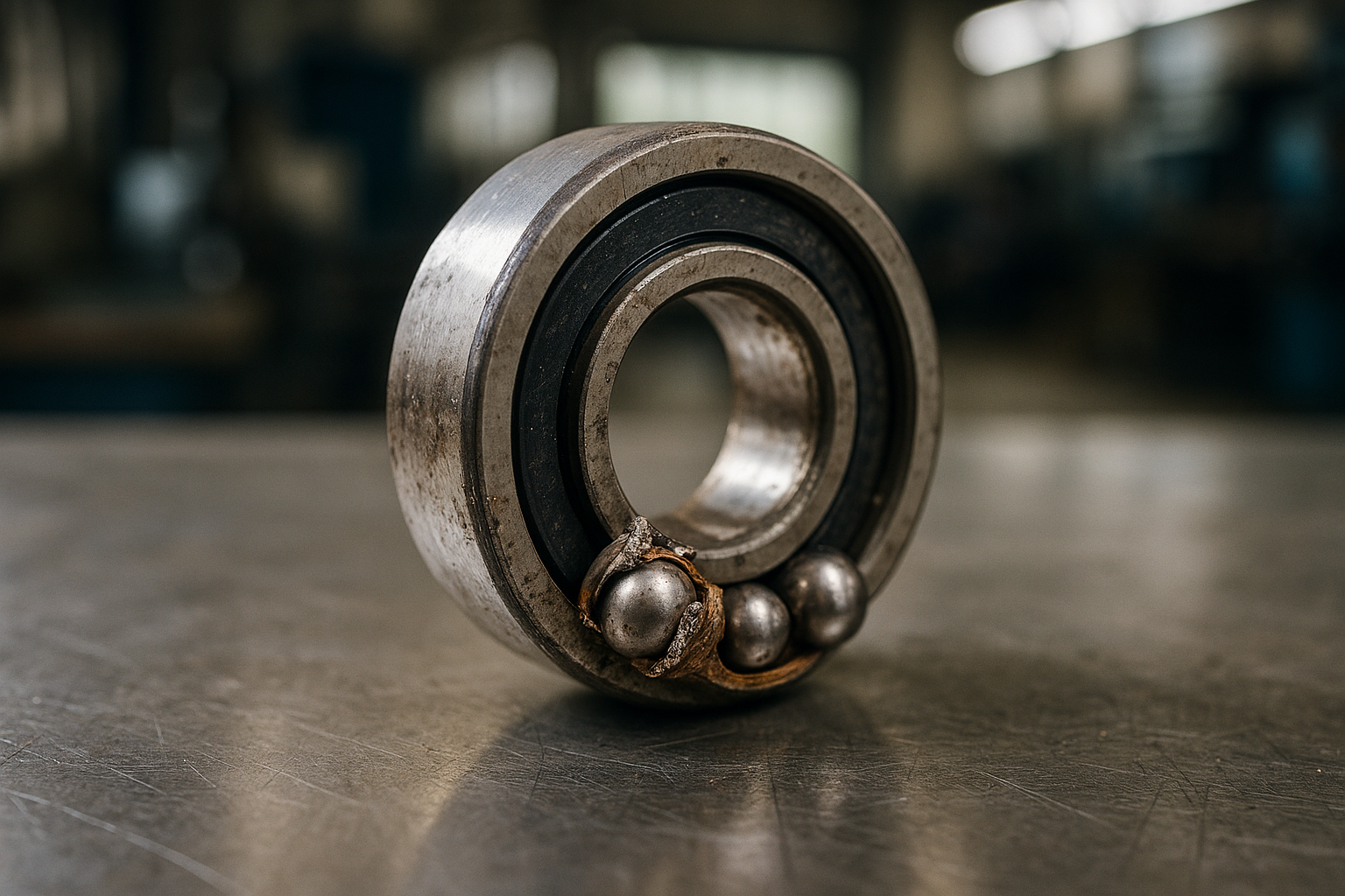
Warranty engineers at the bearing manufacturers see thousands of claims a year and physically inspect very few of them. What they work from is photographs, which means the outcome of your claim is decided largely by how well somebody in your workshop documented a failed component before it went in a box. Photographing a failed bearing systematically is not bureaucracy; it is the difference between a claim assessed on evidence and a claim rejected for insufficient information, and the eight angles below are the ones that carry diagnostic weight.
Set up once, then repeat it every time
Clean neutral background, diffuse light from more than one direction, a scale reference in frame, and a camera held perpendicular to whatever surface you are documenting. Angled shots distort the geometry that the engineer is trying to read and shadows hide exactly the surface texture that distinguishes one failure mode from another. Consistency matters as much as quality: when every claim from your site arrives in the same format, the people assessing them learn to read yours quickly, and that goodwill is worth more than any individual photograph.
The four that establish what the bearing is and what happened to the races
Begin with a full overview showing the complete assembly and the designation markings, which confirms identity and prevents the claim stalling on a question you could have answered. Then the outer ring raceway, photographed around its full circumference with macro focus, noting where damage is heaviest relative to the load zone. Then the inner ring raceway the same way. Then the rolling elements — worth comparing against a new unit from the same deep groove range if you have one to hand — ideally removed and laid out in order, or photographed in place if the bearing will not come apart. The relationship between damage on the two races and on the elements is what identifies the failure family, and a claim missing any of the four forces the engineer to guess.
The four that explain why it happened
The cage next, because cage damage patterns distinguish overload from misalignment from lubrication loss. Then both seal faces, which is where evidence of contamination ingress or lubricant escape lives — a breached seal often explains everything downstream of it. Then the grease or oil, photographed before anybody disturbs it, along with any debris recovered from the housing; unusual colour, texture or particle content frequently identifies the root cause on its own. Finally the installation context: housing bore, shaft seat, adjacent components. That last one protects you, because installation-related rejection is the most common outcome for claims that supply no evidence about the installation. The visual vocabulary for reading all of this is collected in our photo library of thirty failure examples.
What goes around the photographs
Name the files so they are readable without opening them — designation, position, angle. Supply the operating hours, the application, the duty, the lubricant specification and interval, the date the fault was noticed and what the symptoms were. Say plainly what you think happened and why; engineers respond better to a stated hypothesis they can confirm or correct than to a pile of images with no narrative. If the same position has failed before, say so and attach the previous claim, because a repeat pattern moves the conversation from warranty towards application engineering, which is usually where the real fix is.
Knowing which claims are worth making
Not every failed bearing is a warranty case, and submitting the ones that obviously are not costs credibility on the ones that are. Contamination through a seal you can see is damaged, fatigue at the end of a normal service life, damage consistent with misalignment in a housing you know is worn — these are operational findings rather than manufacturing defects. What supports a genuine claim is early failure with no contamination evidence, material or geometry anomalies, or a cluster of identical failures across units from the same batch. Distinguishing honestly between the two categories is also what keeps your manufacturer relationship useful, because the engineer who trusts your assessment will engage properly when something genuinely is defective. Understanding the underlying modes helps, and our guide to identifying failure modes visually covers the distinctions.
Running it through the distributor rather than around them
European distributors handling claims for SKF, FAG or TIMKEN know what each manufacturer’s warranty engineering wants to see and can flag a weak submission before it is filed. They also carry the relationship that gets a stalled claim looked at again. Going direct occasionally feels faster and usually is not. The documentation you have prepared serves both routes equally, which is the argument for doing it properly regardless of how the claim travels — and for keeping the images afterwards, since a failure library built from your own equipment becomes the reference that trains the next technician and the evidence base for the specification conversation described in our notes on maintaining a failure master log.
Need support preparing a warranty submission or reading a failure pattern? Our team works with European maintenance operations on claim documentation and manufacturer engagement. Book a free consultation.