
On a Monday morning a contractor rang the parts counter about an excavator bucket linkage that knocked on every curl stroke, and the teardown of the pivot told a familiar story of spherical plain bearings run dry. The hardened inner ring had worn through its surface treatment, the outer ring showed circumferential bands of scored steel, and the grease nipple on the pin boss had been painted over at the last service. Radial play had grown to the point where the pin was hammering the bearing on every load reversal, which in turn was starting to ovalise the housing bore. The tempting answer is to order the same part number and fit it before lunch. The better answer starts with three questions: in which direction does the load act, does it alternate, and will anybody actually grease the joint at the interval a steel-on-steel design needs? Those questions decide the series, the sliding material and the life you can reasonably expect from the joint.
Why a sliding sphere suits linkages better than a rolling bearing
A spherical plain bearing is two rings with matching spherical surfaces that slide on each other, so the joint can tilt and oscillate while carrying load across a large contact area rather than through a few rolling elements. That large contact area is the whole point. In a linkage, a hydraulic cylinder eye or a steering knuckle the shaft rarely turns a full revolution; it swings through tens of degrees under heavy, often shock-laden load, and frequently under misalignment that the structure itself introduces as it flexes. A rolling bearing in that service suffers false brinelling because the rollers never travel far enough to redistribute lubricant, and its line or point contacts dent under impact. The sliding sphere spreads the load, tolerates edge loading and accepts angular misalignment of several degrees without generating bending stress in the pin or the weld. The price is friction, roughly an order of magnitude above a rolling bearing, so the spherical plain bearings family belongs in slow, oscillating or tilting motion, not continuous rotation at speed.
Radial, angular contact and axial designs under ISO 12240
ISO 12240 divides the family into radial bearings, angular contact bearings, thrust bearings and rod ends, and each geometry answers a different load direction. Radial types such as the GE..ES and GE..UK series carry mainly radial load with a limited axial component in either direction, which suits most pivots, cylinder eyes and linkage joints. Angular contact designs such as the GAC..F series have the sliding surfaces inclined to the axis, so they carry combined radial and one-directional axial load and are normally mounted in opposed pairs, much as taper roller bearings are; their boundary dimensions follow the 320 X taper roller series, which simplifies housing design. Axial types, designated GX in the SKF system and GE..AX or GE..AW at INA, consist of a shaft washer and a housing washer with a spherical interface, intended for axial load with a moderate radial share. The INA GE20-AW, with a 20 mm bore, 55 mm outside diameter and 20 mm height, is a typical compact example for a slewing pivot or a column base that sees mostly vertical load.
Steel on steel or steel on PTFE: the sliding contact sets the maintenance plan
The second decision, and the one that most often goes wrong, is the sliding contact combination. Steel/steel bearings such as the GE..ES series use hardened bearing steel on both rings with a phosphate and molybdenum disulphide treatment for running-in, plus lubrication grooves and holes so grease can be pumped into the contact zone. They tolerate heavy alternating and shock loads well, because each load reversal lets fresh grease into the gap, but they must be relubricated, and on dusty construction or agricultural equipment the grease purge is also what keeps grit out. Maintenance-free designs such as the INA GE20-UK pair a hard-chromed inner ring with a PTFE-based sliding layer on the outer ring. They need no grease and should not be greased, since lubricant interferes with the transfer film the PTFE builds. Their weakness is the opposite of steel/steel: they prefer load acting in one direction, and under strongly alternating load the sliding layer wears much faster, so a reversing cylinder pivot is often better served by a greased steel pair from the INA or SKF ranges.
What the load ratings actually mean
Catalogue tables give a basic dynamic load rating C and a basic static load rating C0 for spherical plain bearings, and both are easy to misread for anyone used to rolling bearings. For a ball or roller bearing, C is defined through rolling contact fatigue and feeds the ISO 281 equation L10 = (C/P)^p in millions of revolutions. A spherical plain bearing has no fatigue mechanism of that kind: it fails when wear, growing clearance or loss of the sliding layer make the joint unusable. C is therefore a reference value, the load at which the bearing reaches a defined life under standardised test conditions, and it is used to calculate the specific bearing load p = K·P/C, where K is a material-dependent factor in N/mm² published by the manufacturer. C0 expresses the maximum static load the bearing can carry without unacceptable deformation of the sliding surfaces or fracture of the rings, and it assumes properly supported rings; in a rod end the housing, not the bearing, is often the real limit. The specific load is what gets compared against the material limit.
Why oscillating life is computed in a different way
Because wear depends on how far the surfaces slide and how hard they press together, life is calculated from specific load and mean sliding velocity rather than from revolutions. For oscillating motion the sliding velocity follows from the sphere diameter dk in millimetres, the half angle of oscillation β in degrees and the frequency f in oscillations per minute: v = 5.82 × 10⁻⁷ · dk · β · f in metres per second, since one full oscillation sweeps through four times β. The product p·v is then checked against the permissible range for the material pair, and the rating life in hours or oscillations is calculated with correction factors for load direction, temperature, sliding velocity and, for steel/steel, the relubrication interval. In practice, a smaller swing angle lowers sliding distance in direct proportion, so linkage geometry that reduces pin travel pays off. And for greased steel bearings, regular relubrication substantially extends calculated life compared with an initial fill only, which is why the grease nipple deserves more attention than it usually gets.
Tilt angle, wide inner rings and sealing
The permissible tilt angle is the misalignment the bearing accepts before the inner ring edge contacts the outer ring or the seal, and it varies with series and sealing arrangement. Standard radial types allow a few degrees up to the low teens, while heavier series with a wider inner ring, such as the GEH 80 ES-2RS, typically trade some tilt for higher load capacity and better support of the pin. That bearing, with an 80 mm bore and 130 mm outside diameter, also illustrates the 2RS suffix: lip seals on both sides keep slurry and dust out of the steel/steel contact, which on construction and agricultural equipment is often the difference between a joint that lasts seasons and one that lasts weeks. Seals do not remove the need for grease; they reduce how much contamination the purge has to expel and they hold grease better under pressure washing. When specifying, check the tilt the structure demands under deflection, not only the nominal geometry, and leave margin: a crushed seal lip becomes a contamination path.
Rod ends: thread hand, housing strength and cylinder heads
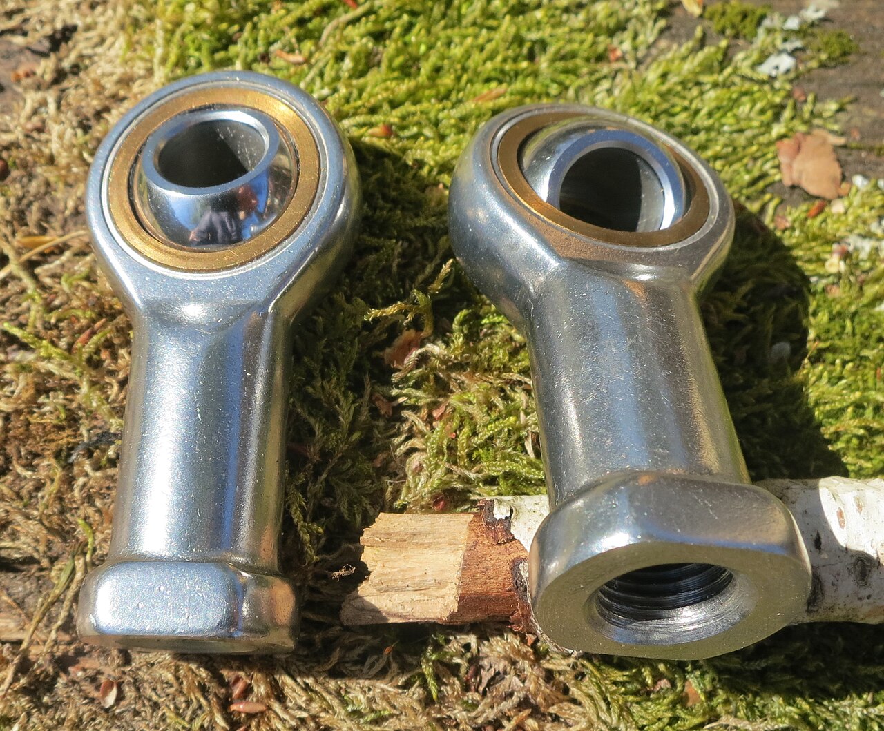
Rod ends combine a spherical plain bearing with an eye housing and shank, either with a female thread (the SI series in the SKF range) or a male thread (the SA series), and in right-hand or left-hand thread so a link can be adjusted by turnbuckle action. They come in steel/steel and maintenance-free versions, mirroring the radial bearings inside, and the full choice sits in our rod end bearings category. The selection trap is that the permissible load of a rod end is usually set by the housing and shank rather than by the bearing’s own rating, and that housing rating is defined for load along the shank axis; side loads at an angle to the eye are not covered and need separate checking. Hydraulic cylinder rod ends add weld-on and clamping versions where thread engagement and the clamping screw torque matter as much as the bearing. On balers, loaders and tipping bodies the thread should always engage fully, because a partially screwed rod end can crack at the first loaded thread root under alternating tension.
Back at the counter, the excavator joint ended up with the same steel/steel radial series rather than a maintenance-free swap, because the bucket pivot sees violent load reversal and a PTFE liner would have worn through quickly; the changes were a sealed version and a reinstated grease point in the service schedule. That is the general pattern for selection. Start from load direction and whether it alternates, which fixes radial, angular contact or axial geometry and points toward steel/steel or steel/PTFE. Then compute specific load and sliding velocity for the real oscillation angle and frequency, and compare p·v with the material limit instead of comparing C with P as you would for a ball bearing. Finally check tilt under deflection, sealing for the environment and, for rod ends, the housing limit. The interval logic in our article on relubrication intervals for real duty cycles applies equally to pivot joints, and mixing greases in a shared lubrication line is a risk covered in our grease compatibility stories.
Not sure whether your pivot needs a greased steel joint or a maintenance-free one? Our team supports load, oscillation and life checks for spherical plain bearings and rod ends in hydraulic, agricultural and construction equipment. Book a free consultation.
Image credits: “2000s rod end bearing M80 or MB0 111 gr” by R. Henrik Nilsson (CC BY 4.0), via Wikimedia Commons.