
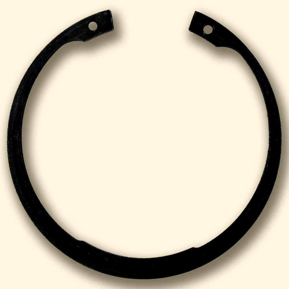
The pump had been running hot for a week before anybody opened it, and when the drive-end cover came off the cause was not the bearing but one of the cheapest parts on the shaft: of all the circlips and retaining rings in that assembly, the external ring locating the bearing inner ring had sprung out of its groove and was lying in the bottom of the housing. With nothing holding it, the inner ring had crept along the shaft under the impeller thrust, the seal had lost its running position and the coupling gap had closed by a few millimetres. The ring itself looked undamaged, which is why the first instinct was to clip it back in and close the cover. The groove told a different story: a rolled edge on the loaded wall and signs of an earlier repair. Small locating parts rarely fail on their own, and understanding why they let go is the quickest way to stop the same pump coming back next month.
Shaft rings and bore rings: what DIN 471 and DIN 472 specify
DIN 471 covers external rings that sit in a groove on a shaft and DIN 472 internal rings that sit in a groove in a bore, and both describe the familiar stamped ring of hardened spring steel with lug holes for pliers. The shaft ring is formed slightly smaller than the groove diameter so it grips the groove bottom when released; the bore ring is formed larger so it presses outward against the groove. That residual tension keeps the ring seated, which is why both standards tabulate groove diameter, groove width and minimum edge distance as well as ring dimensions. The tapered section of the ring, wider at the back than near the lugs, is deliberate: it keeps the ring circular as it is spread or compressed, so it contacts the groove evenly all round. Standard rings carry modest axial load, and heavy-duty versions with a thicker section exist for the same nominal sizes; they are worth stocking for gearbox and pump shafts where thrust is real rather than incidental.
Groove geometry decides more than the ring does
Many retaining ring failures that reach a parts counter are groove failures in disguise. The groove must be cut to the standard diameter and width, with a sharp corner on the load-bearing wall, a small radius only at the groove bottom and no burr thrown up on the shaft surface. If the groove is too deep the ring loses its grip and rattles; too shallow and the ring stands proud, so the load acts further out on the ring and dishes it. The wall that carries the thrust is the one on the far side of the ring from the retained part, and its strength depends on the groove depth, the distance to the shaft end and the yield strength of the shaft material. Tables assume a stated yield strength, so a shaft in softer steel or aluminium carries correspondingly less, and a groove placed too close to the shaft end can shear out as a thin collar of material. Recutting a damaged groove deeper is a common shortcut that quietly changes both ring fit and groove capacity.
Thrust capacity: ring strength versus groove strength
Every circlip location has two separate load limits, and the lower one governs. The first is the load the groove wall can take before it yields, which the tables give for a shaft or housing of stated material strength and which scales with groove depth. The second is the load the ring itself can take before it dishes, shears or springs out of the groove, which depends on the ring section and on how the retained part bears against it. Checking only one is how designs get caught out: a heavy-duty ring in a mild steel shaft with a shallow groove deforms the wall first, the groove edge rolls over, and the ring then levers itself out under a load it could have carried in a harder shaft. Shock loads reduce both limits, and so does speed, because an external ring on a fast shaft tends to lift out of its groove under centrifugal force. The tables give a detachment speed for each ring size, worth comparing with real shaft speed on fans, spindles and fast motor shafts.
Chamfers, corner radii and the bearing’s own edge
The interaction between the ring and the component it retains is where rolling bearings make the problem worse. Ring load tables assume the retained part bears against the ring with a sharp-cornered face close to the shaft. A bearing does not present that face: its inner ring has a chamfer, given in the catalogue as the minimum chamfer dimension r_s, and the ring face touches the circlip only beyond that chamfer, further out from the groove. The load then acts with a lever arm, the circlip tilts and dishes, and the permissible load drops sharply. The standard tables therefore give a reduced ring load together with the maximum chamfer or corner radius the retained part may have; if the bearing chamfer exceeds that value, the ring is overloaded even at moderate thrust. The usual fix is a square-edged DIN 988 support washer or spacer between bearing and ring. The same reasoning lies behind the abutment heights and fillet radii discussed in our article on shaft and housing fits, where the abutment is part of the fit design.
Snap rings on the bearing outer ring
Bearings with a snap ring groove in the outer ring move the idea from the shaft to the housing. In SKF designations the N suffix marks a snap ring groove in the outer ring and NR means the groove comes with the snap ring fitted, the ring dimensions following ISO 464. The snap ring locates the bearing axially against a housing face, so the housing can be a straight through bore without a machined shoulder, which simplifies machining in gearboxes, motors and compact pumps. The deep groove ball bearings with snap ring in our range are the most common case. The limitation is that the snap ring is a thin section loaded on one side; it locates against modest axial load and should be clamped by a cover so it cannot rock, and it is not a substitute for a housing shoulder when axial load is significant. Where a bore circlip provides the location instead, our bore snap rings cover DIN 472 sizes, and the same chamfer rule applies to the outer ring edge.
When a ring is not enough: lock nuts and tab washers
When axial load is heavy, reversing or must be preloaded, a retaining ring is the wrong tool and a threaded location takes over. A KM series lock nut with an MB tab washer clamps the bearing inner ring against a shaft shoulder with a defined force, removes the axial play that any circlip-and-groove stack inevitably leaves, and allows adjustment, which matters for taper roller, angular contact and adapter sleeve arrangements. The washer’s inner tab engages a slot or flat in the shaft thread and one outer tab is bent into a slot of the nut, so the nut cannot back off under vibration. Lock nuts and matching locking tab washers are sized together by thread, and a tab washer is single-use: once a tab has been bent and straightened it cracks at the root. Tightening is the other half of the job, and our guide to torquing a KM lock nut without a slugging wrench explains how to reach the right clamp without hammer damage. A properly tightened nut carries axial load far beyond what a standard ring can manage.
Installation errors and the failure symptoms they leave
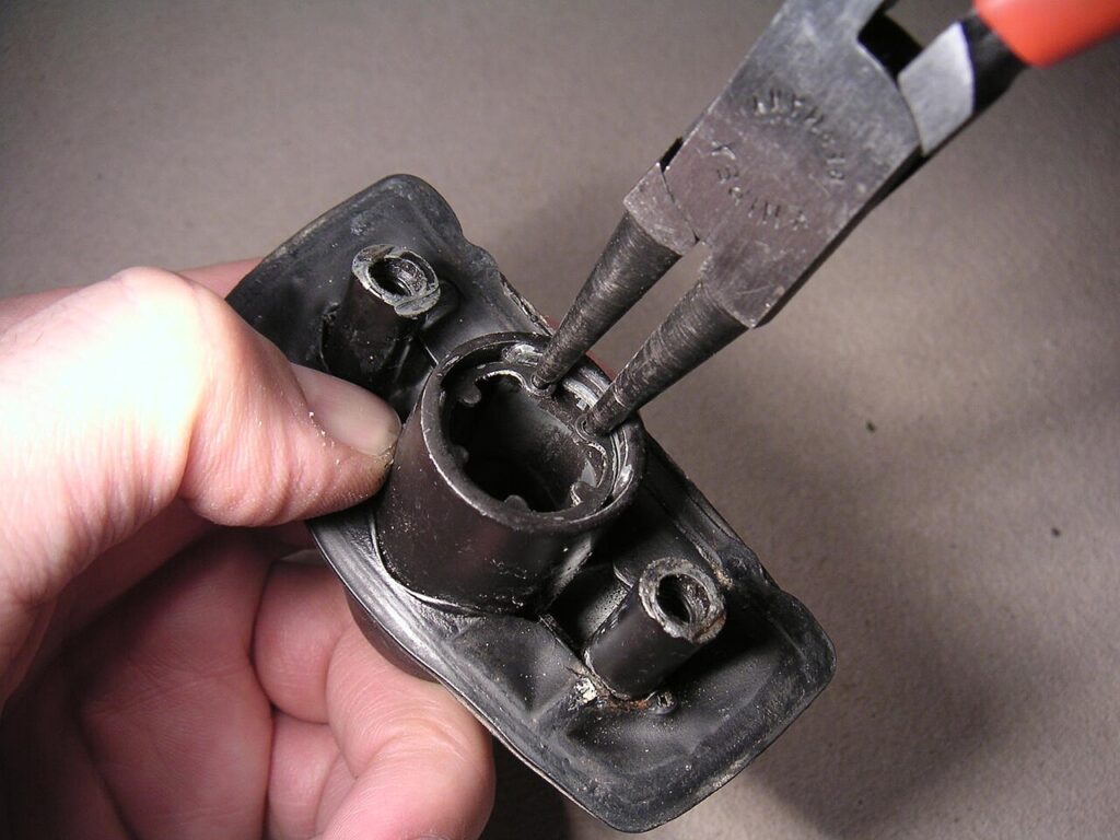
Most ring failures trace back to installation. Over-spreading an external ring beyond the diameter needed to pass the shaft gives it a permanent set, so it no longer grips the groove bottom and rattles or turns; the same happens when an internal ring is over-compressed. Reusing a ring that has already been removed carries the same risk, because the removal itself may have overstretched it. Stamped rings have one rounded and one sharp edge from punching; the sharp edge should face away from the retained part, toward the groove wall that carries the load, so the ring seats squarely against that wall. Fitting with pliers at an angle can leave the ring partly out of the groove, which a quick rotation check would reveal. The symptoms afterwards are consistent: fretting marks on the bearing side face, a groove wall with a rolled edge, a dished ring, axial play heard as a click at load reversal and eventually a bearing that has walked along the shaft. Several of these errors also appear in our article on bearing installation mistakes.
The pump from the opening had a ring of correct size in a groove that had been recut deeper during a previous repair, with a bearing chamfer larger than the ring’s permissible value and no support washer in between. Together these faults let the ring dish and spring out under modest impeller thrust. The practical sequence for any circlip location is short. Confirm the axial load and speed, and if the load is heavy, reversing or needs preload, use a lock nut and tab washer instead. Otherwise check both the groove capacity for the actual shaft material and the ring capacity for the actual chamfer of the bearing, add a square-edged washer if the chamfer is too large, and compare shaft speed with the ring’s detachment limit. Then install a new ring with proper pliers, sharp edge away from the retained part, spread no further than necessary, and rotate it in the groove to confirm it is fully seated. Rings and washers are cheap, which is exactly why they deserve a specification rather than a guess.
Unsure whether a circlip or a lock nut should locate your bearing? Our team supports axial location checks, from DIN 471 and DIN 472 ring sizing to snap ring bearings, lock nuts and tab washers. Book a free consultation.
Image credits: “Snap-ring hg” by Hannes Grobe (CC BY-SA 2.5); “Si-ri-zange-arbeit” by Oxensepp at German Wikipedia (CC BY-SA 2.0 de), via Wikimedia Commons.