
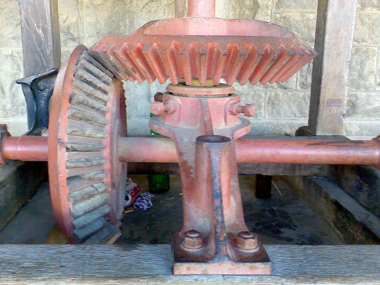
A small packaging machine turns the motion of a horizontal line shaft through ninety degrees to drive a vertical cutter, and after a rebuild the right-angle drive starts to whine and run warm. The bevel gear pair is new, the ratio is right and the bores fit the shafts, yet the tooth flanks already show a bright contact line at the very edge of the teeth. The fitter has simply bolted the gears where the old ones sat, without checking the mounting distance. Bevel gears for right-angle drives are among the simplest ways to change the direction of a shaft, but unlike spur gears they only work properly when both gears sit at an exact axial position, with their pitch cones meeting at a common apex. This article covers how to choose the ratio and module, how much backlash a bevel pair needs, why mounting distance is the critical tolerance and which bearings keep the gears where they belong once the drive is under load.
How a bevel gear pair transmits motion through ninety degrees
A straight bevel gear is a gear cut on a cone instead of a cylinder, with teeth that taper towards the apex of that cone. Two such gears meshing at a shaft angle of 90 degrees roll on each other like two cones touching along a line, and the ratio is set by the number of teeth, exactly as with spur gears. Catalogue pairs are sold as matched sets in standard ratios such as 1:1, 1:2, 1:3 and 1:4, for example the module 1 bevel gear pair Z26/26 with a 1:1 ratio or the module 1 pair Z16/40 at 1:2.5, and they are only intended to mesh with their designated partner because the cone angles depend on the ratio. Straight teeth are simple, inexpensive and suitable for moderate speeds and loads, while spiral bevel gears offer smoother running at higher speeds at a much higher price. For most auxiliary drives, conveyors, agricultural attachments and machine tool accessories, a straight bevel pair from the bevel gears range is the economic choice.
Choosing ratio and module for the job
The ratio follows from the required output speed, but straight bevel pairs become awkward beyond about 1:4 or 1:5, because the pinion becomes very small relative to the wheel, tooth strength drops and undercut appears. Larger reductions are better achieved with a bevel pair followed by a spur gear stage, or with a dedicated right-angle gearbox. The module determines tooth size and therefore load capacity, and a first estimate starts from the torque at the pinion. A drive transmitting 0.75 kW at 1,400 rpm carries about 5 Nm at the pinion, comfortably within the rating of a module 1.5 or 2 catalogue pair in hardened steel, while 4 kW at the same speed, around 27 Nm, typically calls for module 3 or larger depending on width and material. Peripheral speed also matters, since straight bevels become noisy above a few metres per second. When in doubt, choose the next module up: the extra cost is small compared with a broken tooth, and our general gear guide to hub and plate gears on the shaft explains how hub style affects the mounting.
Mounting distance: the tolerance that decides everything
Every bevel gear has a mounting distance, the axial dimension from a reference face on the gear, usually the back of the hub, to the point where the two shaft axes intersect. Catalogue drawings specify this dimension for each gear in a pair, and it must be reproduced on the machine within a tight tolerance, typically a few hundredths of a millimetre for small modules. If the pinion is mounted too far from the apex, contact moves towards the heel, the outer large end of the teeth, and backlash grows. If it is too close, contact shifts towards the toe, backlash disappears and the teeth can jam as the drive warms up. Because the two gears interact, an error in one can be partly compensated by moving the other, but the correct method is to set each gear to its own mounting distance with shims or spacers, then verify. The whine and the edge contact seen on the packaging machine are the classic symptoms of a mounting distance taken from the old, worn gears rather than from the drawing.
How much backlash a bevel pair needs
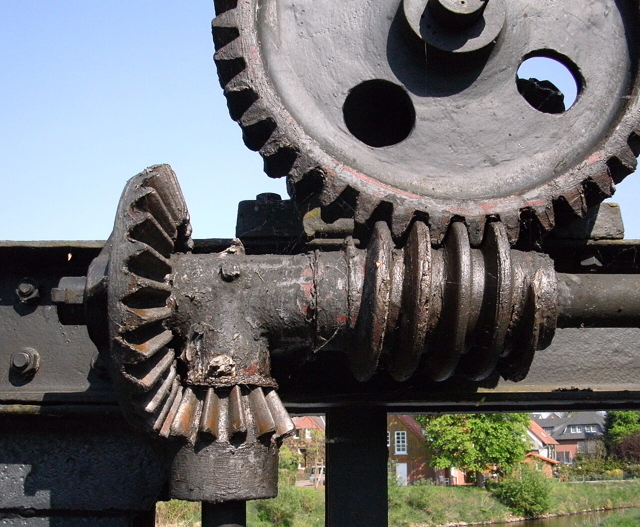
Backlash is the small free play between the teeth of the two gears, and it is essential: it leaves room for the lubricant film, absorbs thermal expansion and accommodates small manufacturing and mounting errors. Too little backlash causes the gears to bind as they heat up, with noise, heat and rapid wear. Too much produces impact at each reversal and rattle in drives that start and stop frequently. For small catalogue modules, sensible values lie between a few hundredths of a millimetre and around a tenth, increasing with module, and the gear manufacturer’s table should be the reference. Backlash is measured with a dial indicator on the tooth flank of one gear while the other is held, and on bevel pairs it is adjusted by moving the gears axially rather than by changing the centre distance, since bevel gears have no centre distance in the spur gear sense. Measuring at three or four positions around the wheel also reveals runout, which often explains why backlash seems to vary as the gear turns.
Checking the contact pattern
The most reliable way to confirm that a bevel pair is correctly mounted is to look at where the teeth actually touch. Paint a thin layer of marking compound on several teeth of the wheel, rotate the pinion by hand in both directions under a light braking load, and examine the imprint. A good pattern on straight bevel gears sits roughly in the middle of the tooth height and slightly towards the toe when unloaded, because under full load the gears deflect and the contact spreads towards the heel. A pattern concentrated at the heel indicates that the pinion should move closer to the apex; a pattern at the toe means it should move away. Contact high on the tooth flank or low near the root points to a mounting distance error on the wheel. Adjust with shims in small steps, repeat the check and record the final shim thickness, since the next rebuild will be much faster with that figure on file. Ten minutes spent on this check prevent most early bevel gear failures.
Bearings, shafts and axial forces
Unlike straight spur gears, bevel gears generate significant axial forces that push each gear away from the mesh, and the bearings must hold them in position or the mounting distance will drift under load. The pinion in particular sees a combination of radial and axial load at a relatively high speed, so it is usually supported by a pair of angular contact ball bearings or taper roller bearings arranged to resist thrust in both directions, while deep groove ball bearings are acceptable on lightly loaded wheels. Overhung pinions should be kept as close to their bearings as possible, because shaft deflection changes the contact pattern under load. Keyways and set screws must be tight, since a hub that creeps along the shaft destroys the setting within hours. Housings that leak oil also deserve attention, and our article on gearbox output shaft seals covers the sealing side of small right-angle drives.
A bevel gear pair is a precise component disguised as a simple one. Ratio and module can be chosen from a catalogue in minutes, but the drive only runs quietly when each gear sits at its mounting distance, the backlash is measured rather than guessed, the contact pattern confirms the setting and the bearings hold everything in place under load. Recording the shim thicknesses and backlash values at assembly makes future replacements quick and repeatable. Italian manufacturers such as CHIARAVALLI supply catalogue bevel pairs in a wide range of modules and ratios, and our overview of the CHIARAVALLI power transmission range shows how gears, sprockets and pulleys from one source simplify ordering. When a worn pair has to be replaced, always replace both gears together, because a new pinion running against an old wheel reproduces the wear pattern of the old pair almost immediately.
Choosing a bevel gear pair or replacing a worn one on a right-angle drive? Our team helps match module, ratio, bore and mounting distance from catalogue stock, and checks the bearings that must carry the axial loads. Book a free consultation.
Image credits: “Bevel gears on grain mill at Dordrecht, Eastern Cape” by Gregory David Harington (CC BY-SA 2.5); “Wehr Quintusstraße Getriebe1” by ChristianSW (CC BY-SA 3.0), via Wikimedia Commons.