
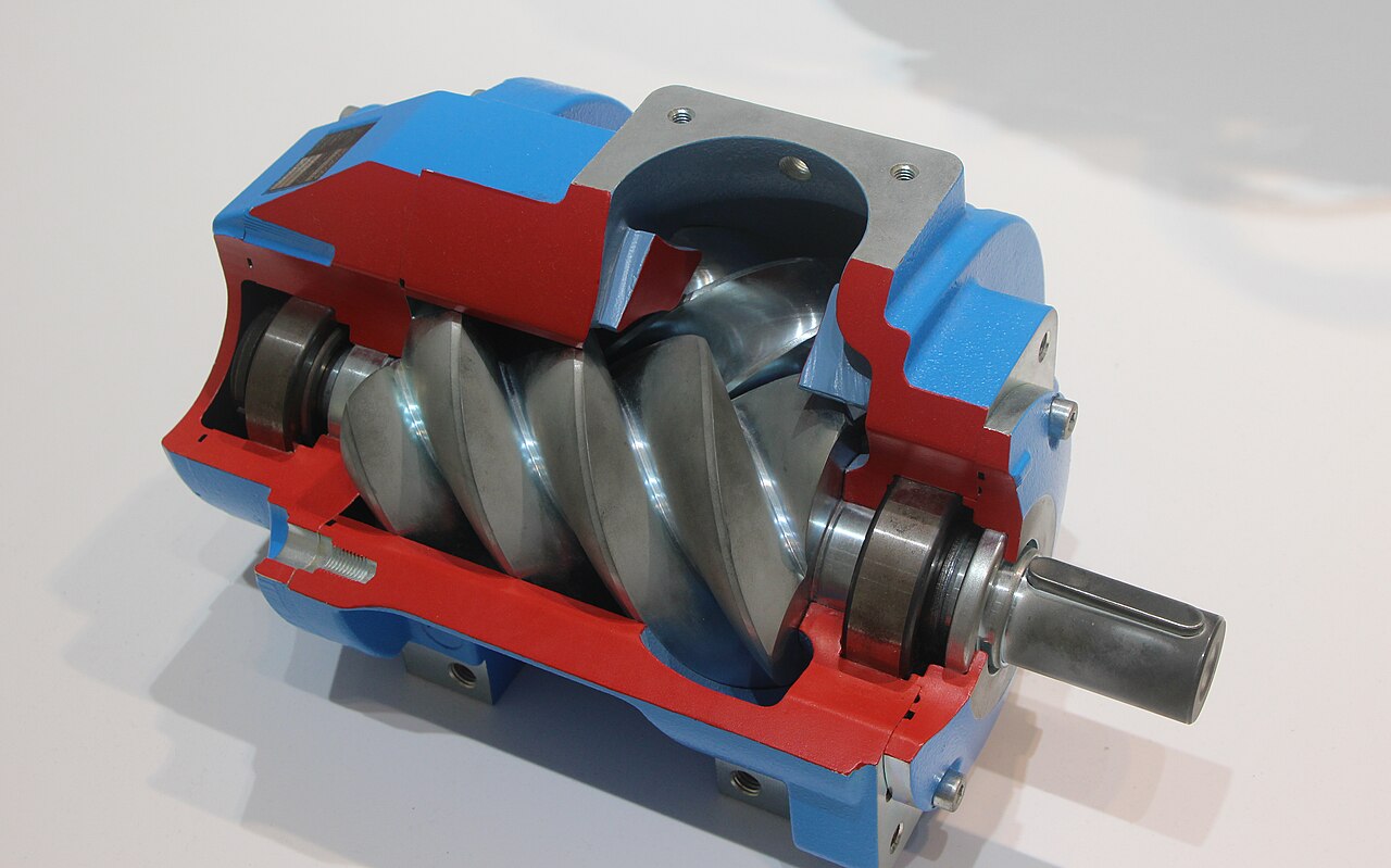
The compressor in the corner of the plant has run for years with little more than oil and filter changes, until one morning the discharge temperature climbs, the motor current rises and a faint metallic note appears over the usual hum. When the airend is opened, the rotors show witness marks on their tips and the thrust bearing at the discharge end has lost its preload. Nothing broke suddenly; the bearing simply let the rotor move a few hundredths of a millimetre more than the design allows. That is the essence of screw compressor bearings: they do not only carry load, they hold two helical rotors in position with clearances measured in microns. Understanding why the bearing arrangement looks the way it does, with cylindrical rollers for the radial load and angular contact ball bearings for the thrust, is the first step towards replacing them correctly and getting the full life out of an expensive airend.
How a screw compressor loads its bearings
A twin-screw compressor traps air or gas between two meshing helical rotors and the housing, and compresses it as the trapped volume moves towards the discharge port. The pressure acting on the rotor lobes produces two kinds of load. The radial load pushes the rotors apart and towards the housing wall, and it grows with the difference between discharge and suction pressure. The axial load comes from the same pressure acting on the helical surfaces and on the rotor ends, and it pushes each rotor towards the suction end with a force that can be several times the radial load on a high-pressure machine. Both loads change with operating conditions, so a compressor running at partial load, unloading and reloading many times an hour subjects its bearings to cycling forces. Unlike most industrial machines, the airend has very little tolerance for movement, because any shift of a rotor changes the clearances that keep air from leaking back and keep metal from touching metal.
Cylindrical roller bearings for the radial load
The radial loads at both ends of each rotor are usually carried by single row cylindrical roller bearings, because they offer the highest radial capacity for their cross section and run well at the speeds typical of compressors. Designs with ribs on one ring only, such as the NU type, let the shaft move axially relative to the housing, which is exactly what is wanted when another bearing takes the thrust. Their behaviour under combined loads is covered in detail in our article on NU, NJ, N and NUP cylindrical roller bearings. In compressors these bearings typically have tight radial internal clearance and often machined brass or high-strength polymer cages, selected according to temperature and lubricant. When replacing them, the clearance class and cage suffix should match the original exactly, because the radial clearance contributes directly to the rotor-to-housing gap. Our range of single row cylindrical roller bearings includes the common compressor sizes.
Angular contact pairs and the thrust problem
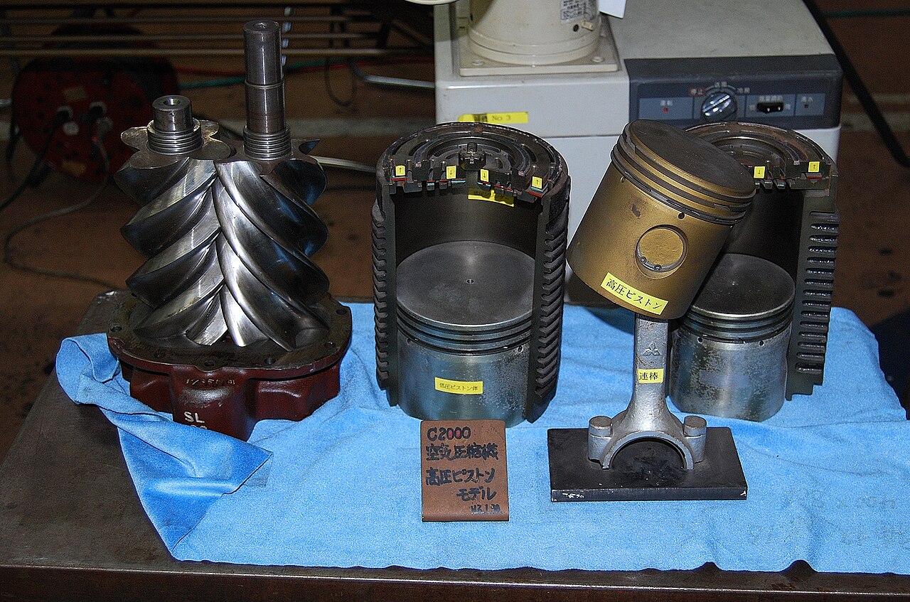
The axial force is the hardest part of the design. It is usually taken at the discharge end by angular contact ball bearings with a large contact angle, often 40 degrees, arranged as a tandem pair or set so that two or more bearings share the main thrust. A further bearing, sometimes mounted back-to-back with the set, takes the reverse thrust that appears briefly during start-up, shutdown or unloading. Some designs add a balance piston fed with discharge pressure to reduce the net thrust on the bearings. Whatever the layout, the bearings must be universally matched or supplied as a matched set with controlled preload or axial clearance, which is why the advice in our workshop check of angular contact universal pairs applies directly. Mounting them in the wrong orientation reverses the load path and can destroy a set within hours, so arrangement markings on the outer rings must be followed precisely during assembly.
Preload, axial play and rotor clearances
Rotor end clearance at the discharge end is commonly only a few hundredths of a millimetre, and it is set by the position of the thrust bearings. Too much axial play allows the rotor to move towards the discharge face under changing load, increasing leakage and risking contact, while too much preload raises bearing temperature and shortens life. That is why compressor manufacturers specify the bearing set, the shims and the measurement procedure together. In practice the airend is assembled, the axial position measured and corrected with shims, and the result checked against the specified window. The principles are the same as those explained in our article on setting bearing preload in a paired mount, but the tolerances are tighter. If a set must be replaced, all bearings in it should be replaced together with exactly the same arrangement and preload class, from one manufacturer such as SKF or FAG.
Lubrication: oil-injected and oil-free designs
In oil-injected compressors the same oil that seals and cools the compression process also lubricates the bearings, often through dedicated channels. That oil carries heat, dissolved gas and, in humid conditions, condensed water, so its condition decides bearing life as much as the bearing design does. High discharge temperatures oxidise oil, while running too cold lets water accumulate and corrode raceways. Oil-free compressors separate the compression chamber from the bearings with shaft seals, and the bearings run on a separate oil circuit, which makes seal condition critical. In both cases the oil specification, change interval and filter quality given by the manufacturer should be followed, and topping up with a different oil should be avoided, because incompatible additive packages can foam, form deposits or lose their protective properties. Oil analysis, including water content and wear metals, is one of the best early indicators of bearing distress.
Typical failure modes to watch for
Most screw compressor bearing failures fall into a few recognisable patterns. Thrust bearing fatigue appears as spalling on one side of the raceways and is usually linked to high discharge pressure, frequent load cycling or an incorrect preload. Corrosion and etching come from water in the oil, often in machines that run at low load or in cold rooms. Smearing on cylindrical roller bearings happens when lightly loaded rollers slide rather than roll, typically during unloaded running. On machines with variable speed drives, electrical erosion and fluting can appear on the motor and sometimes on airend bearings, as discussed in our article on fluting from shaft currents in inverter motors. Each pattern points to a different root cause, so failed bearings should always be kept, cleaned and inspected rather than discarded, because they carry the evidence needed to stop the next failure.
Planning an airend bearing replacement
Because of the tight tolerances, an airend bearing change is closer to a rebuild than a routine bearing swap. Before ordering, collect the complete designations of every bearing, including cage, clearance, contact angle and arrangement suffixes, and check them against the manufacturer’s parts list rather than the dimensions alone. Plan for new seals, shims and lock nuts, and make sure the workshop has the tools to heat bearings evenly and measure axial position accurately. For compressors that run continuously, keeping a matched set of angular contact ball bearings and the cylindrical roller bearings in stock is often cheaper than one extra day of rented air. After the rebuild, monitor vibration, discharge temperature and oil condition closely during the first weeks, because early problems with preload or alignment usually show themselves quickly and can be corrected before they become costly.
Screw compressor bearings work in a demanding niche where load, temperature and position all matter at once. Cylindrical roller bearings carry the radial forces, angular contact sets fight the thrust and hold the rotors where the designer intended, and the oil keeps everything alive. When replacing them, match designations exactly, respect the arrangement and preload, and treat oil quality as part of the bearing system. Done that way, an airend that has already given years of service can deliver many more, and the morning when the discharge temperature starts to climb becomes a planned rebuild rather than an emergency. Keeping the bearing designations, shim values and measured end clearances from each rebuild in the machine file makes the next one faster and far less dependent on the memory of a single technician.
Rebuilding a screw compressor airend? Send us the bearing list or the compressor model, and our team will check designations, arrangements and availability for a complete set. Book a free consultation.
Image credits: “Screw compressor Deutsches Museum” by Wikisympathisant (CC BY-SA 4.0); “Air compressor screw and piston” by Toshinori baba (CC BY-SA 3.0), via Wikimedia Commons.